


Chapter 5 CANopen
Manual VIPA System 200V
5-14
HB97E - IM - Rev. 06/29
•
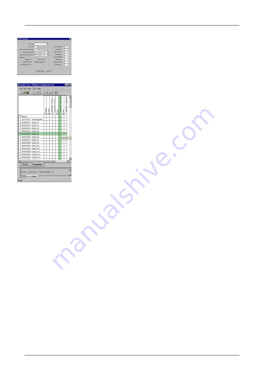
Right click onto the master and open the VIPA specific dialog "Set PLC
Parameters". Here you may adjust the diagnosis behavior and the
address ranges that the master occupies in the CPU.
Under "Slot number" type the slot no., where your CAN master is
plugged. At export, WinCoCT creates the according DB no. + 2000.
•
Change to the register "Connections" in the main window. Here the
process data are shown in a matrix as inputs (1
st
column) and as
outputs (1
st
row).
To monitor the process data of a device with a "+" click on the according
device.
•
For helping you, you may only define a connection when the appearing
cross has green color. Select the according cell with the mouse pointer
in row and column in the matrix and click on it.
→
The cell is marked
with a " ". You can control the connection by changing into "Devices",
click on the master and monitor the process image of the master via
"Device Access".
•
Save your project.
•
Via
File
>
Export
your CANopen project is exported into a wld-file. The
name is the combination of project name + node a ID
M
a
s
ter/
Sl
a
v
e.
Now your CANopen project engineering under WinCoCT is ready.
•
Start the SIMATIC manager from Siemens with your PLC project and
open the wld-file via
File
>
Memory Card File
>
open
.
•
Copy the DB 2xxx into your block directory.
•
Start the hardware configurator from Siemens with a new project and
insert a profile rail from the hardware catalog.
•
Place the following Siemens CPU onto plug-in location 2:
CPU 315-2DP (6ES7 315-2AF03-0AB0). For the project engineering of
the VIPA standard CPUs of the Systems 100V, 200V, 300V and 500V
please use starting with the firmware version 3.5.0 the CPU
6ES7-315-
2AF03
V1.2 from Siemens from the hardware catalog!
•
If for example your CAN master module is directly placed beside the
CPU, you project your CAN master on plug-in location 4.
•
Starting with plug-in location 5, you include your System 200V modules
on the standard bus in the plugged sequence.
•
Parameterize your CPU res. the modules when needed. The parameter
window is opened when you double click on the according module.
•
Save your project and transfer it to your CPU.
After the transfer the CPU recognizes the DB for the CAN master and
passes the contents of the DB on to the according CAN master at STOP-
RUN change.
Import into PLC
program and
transfer to CAN
master
Содержание System 200V IM Series
Страница 1: ...Manual VIPA System 200V IM Order No VIPA HB97E_IM Rev 06 29...
Страница 2: ...Lerrzeichen...
Страница 6: ...About this manual Manual VIPA System 200V Subject to change to cater for technical progress...
Страница 10: ...Contents Manual VIPA System 200V iv HB97E IM Rev 06 29...
Страница 18: ...Chapter 1 Basics Manual VIPA System 200V 1 6 HB97E IM Rev 06 29...
Страница 136: ...Chapter 3 Profibus DP Manual VIPA System 200V 3 104 HB97E IM Rev 06 29...
Страница 338: ...Chapter 8 Ethernet coupler Manual VIPA System 200V 8 34 HB97E IM Rev 06 29...
Страница 344: ...Chapter 9 Bus expansion modules IM 260 IM 261 Manual VIPA System 200V 9 6 HB97E IM Rev 06 29...


