background image

This document and the information contained herein, is the exclusive property of Verlinde S.A.S. and represents a non-public, confidential and proprietary trade secret that 
may not be reproduced, disclosed to third parties, altered or otherwise employed in any manner whatsoever without the express written consent of Verlinde S.A.S. 
Copyright © (2013) Verlinde S.A.S. All rights reserved. 

06/2015

S

U

P

D

O

C

_

S

M

_

Q

1

1

0

1

0

0

-0


 P

S

1

7

9

8

4

 2

4

.6

.2

0

1

5


O

ri

g

in

a

in

s

tr

u

c

ti

o

n

s


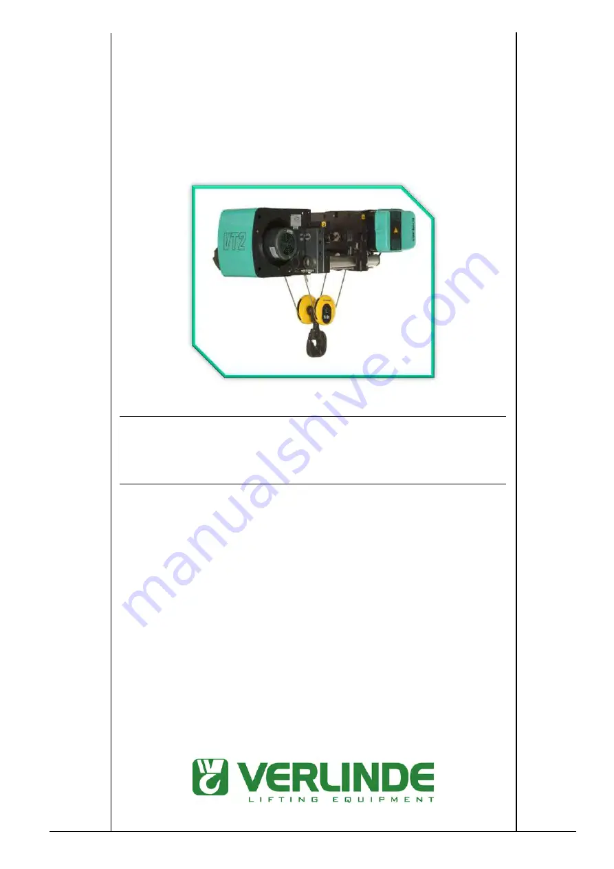
EUROBLOC


SERVICE MANUAL FOR HOIST 


English   SUPDOC_SM_Q11-0.ORD   24.6.2015 

-   -   -   - 

003014    06.2015 


Содержание EUROBLOC VT

Страница 1: ...hat may not be reproduced disclosed to third parties altered or otherwise employed in any manner whatsoever without the express written consent of Verlinde S A S Copyright 2013 Verlinde S A S All righ...

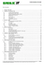
Страница 2: ...N 12 4 1 Manufacturer 12 4 2 Hoist series 13 4 3 Hoist Identification Data 14 4 4 Verlinde code example Verlinde VT Factory Q 16 4 5 Motor Identification Data 17 5 GENERAL ABOUT MAINTENANCE 19 5 1 Ser...

Страница 3: ...erated limit switch 129 7 2 Rope reeving system 136 7 2 1 Standard reevings one rope from drum 136 7 2 2 True vertical reevings two ropes from drum 140 7 2 3 Machinery reevings 143 7 2 4 Rope sheave m...

Страница 4: ...al product updates 12 2011 KHHJII Whole document Updates and corrections 10 2013 XJAASKPA Whole document Updates and corrections Integrating partial GO as part of maintenance tasks Instructions on rep...

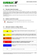
Страница 5: ...substitute for proper training but provides recommendations and methods for safe and efficient service 2 2 Symbols used in this manual Readers should familiarize themselves with the following symbols...

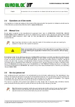
Страница 6: ...elease and hold manufacturer harmless from any and all claims demands AND damages regardless of their nature or type losses and expenses whether known or unknown present or future any and all liabilit...

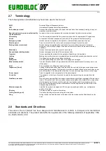
Страница 7: ...small movements by repeatedly and momentarily pressing the direction control Bridge The bridge main girder moves along the runway Main girder The main girder bridge is connected to the bridge end carr...

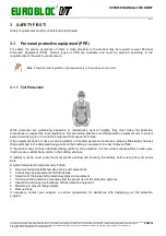
Страница 8: ...ired by local regulations Fall prevention practices and fall protection equipment aim to protect personnel working on or around the equipment from exposure to falls If the equipment does not have a se...

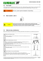
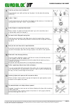
Страница 9: ...may result in exposure to electric shocks 3 4 Safety during maintenance Before and during product maintenance the following precautions should be taken by maintenance personnel 1 Choose a safe workin...

Страница 10: ...o operational status Ensure that any safety devices which have been bypassed for testing purposes have been restored to full operational status before allowing the product to be used for normal operat...

Страница 11: ...cy The owner must ensure that the operators are fully aware of the applicable lockout tagout practices Lockout tagout procedures are primarily intended to protect personnel by preventing accidental st...

Страница 12: ...inde S A S All rights reserved 06 2015 4 IDENTIFICATION This manual contains information for several hoist types components and options The information in this manual is identified by individual featu...

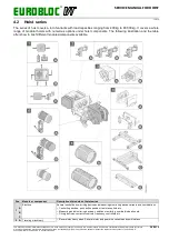
Страница 13: ...ities ranging from 400 kg to 80 000 kg It covers a whole range of modular hoists with numerous options under hoist components The following illustration and the table after show in brief different mod...

Страница 14: ...er trolley C Double girder trolley Low C Double girder trolley Medium C Double girder trolley High D Two hoist trolley Fixed connection variants E Fixed hoist E Machinery hoist 6 Reeving system Severa...

Страница 15: ...and proprietary trade secret that may not be reproduced disclosed to third parties altered or otherwise employed in any manner whatsoever without the express written consent of Verlinde S A S Copyrig...

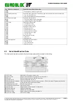
Страница 16: ...olley low DES01 value F L H M W N T M B X J Normal headroom trolley parallel Normal headroom trolley perpendicular Machinery hoist Swivelling trolley Special Special low headroom trolley DES01 value N...

Страница 17: ...other motor information such as motor type are stated on the motor rating plate which is located on the motor Hoisting motor Note Hoisting motor data plate may also be located on the side plate of the...

Страница 18: ...l number Unique number which identifies the unit 3 Input Acceptable main voltage range and frequency that the product can be connected to 4 Output Voltage range the product is able to provide at a spe...

Страница 19: ...product s manufacturer CAUTION Never wash the crane or hoist with chemical products or high pressure water jets as they can cause problems like detaching of the stickers and water entering inside the...

Страница 20: ...rized service personnel or experienced service technician authorized by the product s manufacturer Inspections must be carried out according to manufacturer s instructions Note If the working environm...

Страница 21: ...non public confidential and proprietary trade secret that may not be reproduced disclosed to third parties altered or otherwise employed in any manner whatsoever without the express written consent of...

Страница 22: ...ORKING PERIOD SWP CALCULATION to calculate the remaining SWP 5 3 1 General Overhaul In the GO service the product is assigned with a new runtime based SWP provided that it is safe to continue the oper...

Страница 23: ...roduced disclosed to third parties altered or otherwise employed in any manner whatsoever without the express written consent of Verlinde S A S Copyright 2013 Verlinde S A S All rights reserved 06 201...

Страница 24: ...peration of the hoist is taken into account in SWP If the hoist is provided with a condition monitoring unit the SWP value can be read from the unit display Refer to the more detailed instructions tha...

Страница 25: ...ixed Visually check that covers are not bent or cracked Fix or replace if needed Stickers and markings 10 12 Inspect the condition and readability of warning stickers and other stickers and markings V...

Страница 26: ...Limit Distance 10 12 Verify Down Limit Distance When the hook block is in the Down Limit Switch Activation point verify that there is a minimum number of wraps of rope on the drum according to the st...

Страница 27: ...he fasteners are fixed properly Check the bar for possible signs of wear burn marks oxidation cracks or any other general damage Main isolation switch Main runway disconnect switch Inspect the main is...

Страница 28: ...nt Interval Inspection and maintenance task Interval is SWP reduction or calendar months See further instructions Emergency stop 10 12 Check that the emergency button is clean and not damaged Push in...

Страница 29: ...no visible damages Check the correct amperage rating Braking resistors with some frequency converter models 10 12 Clean all dust or dirt from the braking resistors Hoisting frequency converter 10 12 C...

Страница 30: ...n the gear shaft Hoisting brake Replacement of a hoisting brake Traveling brake 10 12 20 24 Inspect that there is no visible damage Check that the outside surface of the brake is clean Drive with load...

Страница 31: ...sound of the rope drum bearings and check that the rope drum does not touch with the machinery end plates or other parts Lubricate the drum bearings on both sides of the drum if not life time lubrica...

Страница 32: ...ng issues Check if the hook block tries to rotate remove the rotation by reassembling the end fixing and by rotating to the opposite direction Inspect that the reeving balancing tilts freely in two ro...

Страница 33: ...running sound of bearings If necessary lift the trolley and test by hand the free and smooth rotation of trolley wheels Check that the wheels are correctly aligned and inspect for possible wear that...

Страница 34: ...am operates correctly when lifting and lowering Test that the limit switch stops the motions Lubricate the actuator and the cam mechanism if necessary Construction of holding brake Construction of ove...

Страница 35: ...ompatible lubricant can damage the gearing or bearings Use only lubricants recommended by the product s manufacturer See the lubricant tables for more information Use only fresh oil grease Different k...

Страница 36: ...st be depressurised for the grease to be able to penetrate 9 While lubricating check the functioning of the bearings and observe whether there is any bearing slackness 10 The specified lubrication per...

Страница 37: ...icated H3 Hoisting transmission Annual H4 Rope Monthly Annual H5 Rope drum bearings Annual if not life time lubricated H6 Rope guide Annual K Hook thrust slide bearings Annual if not life time lubrica...

Страница 38: ...without the express written consent of Verlinde S A S Copyright 2013 Verlinde S A S All rights reserved 06 2015 6 2 4 Lubrication Charts Double girder trolley Pos Component Intervals H1 Rope anchorage...

Страница 39: ...herwise employed in any manner whatsoever without the express written consent of Verlinde S A S Copyright 2013 Verlinde S A S All rights reserved 06 2015 6 2 5 Lubrication Charts Fixed hoist Pos Compo...

Страница 40: ...4 Rope Monthly Annual H5 Rope drum bearings Annual if not life time lubricated H6 Rope guide Annual H1 Rope anchorage Lubricate the pivot joint of the lever mechanism the suspension support of the rop...

Страница 41: ...stallation Trade name and number Factory installed Almagard 3752 Alternative Shell Gadus S3 High Speed Coupling Grease Alternative Neste Avora H3 Drum gear rim Installation Trade name and number Facto...

Страница 42: ...will suffice Installation Trade name and number Factory installed Mobilith SHC460 Alternative Shell Gadus S5 V220 Alternative Neste Synlix Alternative Castrol S H6 Rope guide for hoist frame size VTs...

Страница 43: ...ired The breather plug can be used as a filling hole if it becomes necessary to top up the grease Installation Trade name and number Factory installed Mobilux EP 004 Alternative Shell Gadus S1 Low Spe...

Страница 44: ...EN2 900 ml 31 7 fl oz Imperial 406 mm GEN3 1400 ml 49 3 fl oz Imperial 608 mm GEN4 2500 ml 88 0 fl oz Imperial 6 2 8 Lubricant volumes drum rim gear Drum diameter Volume 243 mm 50 ml 1 8 fl oz Imperia...

Страница 45: ...ng gearbox and motor can be found in their respective sections Hoisting machinery Frame size VTs VT1 VT2 VT3 1 Hoisting gearbox 2 Hoisting motor 3 Hoisting machinery 4 Rope drum assembly 5 Limit switc...

Страница 46: ...prevent it from rotating Remove hoisting limit switch assembly and cover 5 Remove the screw 7 so that the lifting device can be attached 3a 3b VT1 Install the lifting device E to the hoisting gearbox...

Страница 47: ...f Verlinde S A S Copyright 2013 Verlinde S A S All rights reserved 06 2015 5 6 Remove the fan cover 9 Remove the screws in order to remove the hoisting motor 2 from the gearbox 1 Remove the coupling 1...

Страница 48: ...to the gearbox 1 with three screws Lift the hoisting motor 2 above the gearbox Pass the power cables and the brake cable through the holes in the hoisting gear 5 6 Ensure the motor shaft engages with...

Страница 49: ...er E Install the countersunk screw 7 Install the hoisting limit switch assembly 5 with the cover Hoisting machinery Frame size VT4 VT5 1 Hoisting gearbox 2 Hoisting motor 3 Hoisting machinery 4 Juncti...

Страница 50: ...disassemble the hoisting limit switch assembly 5 open first the switch cover and disassemble the wiring before removing the whole limit switch assembly If you disassemble only the hoisting motor it i...

Страница 51: ...the sleeve 11 at the base of the hoist axle Apply silicone adhesive on the seal plate and end plate joint and on the sleeve 2a 2b Use the lifting device A to install the gearbox Align the gearbox axl...

Страница 52: ...im and coupling 7 thoroughly on the reducer gear shaft A coupling that has a groove outside MUST be installed with the groove facing the gear Couplings in some gears of bigger size do not have any gro...

Страница 53: ...t of Verlinde S A S Copyright 2013 Verlinde S A S All rights reserved 06 2015 7 1 2 Rope drum 7 1 2 1 Construction of rope drum for hoist frame size s VT1 VT2 VT3 1 Rope drum 2 Needle bearing strip be...

Страница 54: ...he inspection hole 6 Hoist frame size VTs VT1 VT2 VT3 The drum bearing through the lubrication point A or B When lubricating the drum it is recommended to mark the starting point in order to know when...

Страница 55: ...ooves on the worn area of the rope drum Measure the clearance between the groove and the drum groove gauge with a wire feeler gauge Compare the measurement result with the result from the non worn are...

Страница 56: ...ia mm mm mm mm The clearance between the drum bearing groove gauge and the bearing running surface 0 2 0 2 0 2 0 2 In some hoist models 6 2 old default rope or 6 5 heavy duty rope or 6 7 rotation resi...

Страница 57: ...ope CAUTION Take into account the weight of falling rope when removing the clamps Reassembly 1 2 A Lubricate the drum surface B Apply the thread locking to bolts Start reeving placing one wrap around...

Страница 58: ...ping into the wrong groove CAUTION Check the correct installation When installing a rope install a left hand lay on the right hand groove and a right hand lay on the left hand groove When installing a...

Страница 59: ...shaft 3 Put the second half of bearing 4 to the upper intermediate beam and install the bearing housing 2 and the fixing screws 1 Do the same to lower bearing Switch ON the power supply to the hoist t...

Страница 60: ...he connector rod 5 along with the rope guide 1 Reassembly 1 2 Insert the connector rod 5 into the rope guide 1 Install the connector rod 5 with the rope guide 1 on the drum Place the rope guide so tha...

Страница 61: ...All rights reserved 06 2015 5 6 Switch ON the power supply to the hoist Test the rope guide for smooth operation by running the hoist both directions Install the machinery covers 7 1 4 3 Construction...

Страница 62: ...h the rope guide 1 on the drum Place the rope guide so that the rope passes through the slot in the rope guide and the guiding surface of the rope guide sits in the groove next to the last rope wrap o...

Страница 63: ...opyright 2013 Verlinde S A S All rights reserved 06 2015 7 1 4 4 Construction of pressure roller for hoist frame size VT1 VT2 VT3 1 Pressure roller 2 Intermediate shaft Disassembly 1 2 Lower hook to t...

Страница 64: ...Place the springs and the fixing nuts 4 around the fixing screws 3 4 Adjust the spring pre stress to length L 14 mm by tightening the nuts 4 on the fixing screws L 14 mm Adjust the pressure roller 1 t...

Страница 65: ...rlinde S A S All rights reserved 06 2015 3 4 Adjust the spring pre stress to length L 14 mm by tightening the nuts 4 on the fixing screws L 14 mm Adjust the screw 3 so the raising the roller by 3 4 mm...

Страница 66: ...S All rights reserved 06 2015 Disassembly 1 2 Lower hook to the floor and switch OFF the power supply to the hoist Remove the machinery covers Remove the guide bearings 3 on the rope guide Remove one...

Страница 67: ...h the screws 7 and springs 8 Make sure that there are at least 2 5 mm of spacer plates 5 between the rim halves at both ends Tighten the screws until the springs are compressed to a length of 15 mm No...

Страница 68: ...ch ON the power supply to the hoist 7 8 Test drive the hoist while observing the rope guide travel through the whole height of lift Test the tightness of the rope guide at both the upper and lower hoi...

Страница 69: ...in any manner whatsoever without the express written consent of Verlinde S A S Copyright 2013 Verlinde S A S All rights reserved 06 2015 1 U shaped rod 2 Guide frame lower half 3 Guide frame upper ha...

Страница 70: ...frame from the drum groove Remove two screws in order to remove the guide element 7 from the hoist intermediate shaft and remove it from the upper half 3 of the guide frame 5 Remove the upper half 3 o...

Страница 71: ...ext to the groove from which the rope leaves the drum With the rope passing through both the joint plate 4 and the lower half 2 of the guide frame fix the joint plate and the lower half together with...

Страница 72: ...lied in the up or down direction Rope guide test drive and final adjustment Test drive the hoist in both up and down direction and check that the rope guide travels through the whole height of lift wi...

Страница 73: ...1 4 7 Rope pressure roller for hoist frame size VT4 VT5 1 Upper pressure roller 2 Intermediate shaft 3 Spring 4 Lower pressure roller 5 Limit switch Disassembly 1 2 Lower hook to the floor and switch...

Страница 74: ...bearing assembly on the fixing plate 15 Then remove the bearing assembly from the fixing plate to separate the sleeve 13 and the bearing 14 Reassembly 1 2 Assemble the bearing assembly A including the...

Страница 75: ...oller assembly with the screws 8 Install the screw 6 lightly without tightening Tilt the upper pressure roller 1 and place the assembly over the intermediate shaft 2 Install the screw 7 Tighten both s...

Страница 76: ...ch Disassembly 1 2 Lower hook to the floor and switch OFF the power supply to the hoist Remove the machinery covers Unscrew the limit switch adjustment screw 3 a few turns and remove the limit switch...

Страница 77: ...n the screw with the bearing 10 to the torque arm 8 3 4 Clean and lubricate the bearing 10 surfaces on both ends of the pressure roller 1 Press the correct torque support to the correct end of the gui...

Страница 78: ...ock into position with nut 5 Install the limit switch 4 to the attachment plate Insert the limit switch adjustment screws 3 with springs into the torque arm threaded holes 9 Attach the limit switch wi...

Страница 79: ...duty rope guide When replacing an old style rope guide with a new style rope guide in a true vertical lift hoist or in a machinery hoist the hoisting limit switch setting for the hook lower position...

Страница 80: ...The lubricant for the hoisting gear is semi fluid grease When used in conformance with the operating group classification of the hoist the gearbox lubricant is not changed during the Safe Working Per...

Страница 81: ...ox cover 5 Fixing screws for gearbox 6 Fixing plate for gearbox 7 Gearbox plug 8 Coupling 7 1 5 1 Replacement of a sealing set for the hoisting gearbox of frame size VTs VT1 VT2 VT3 If the gearbox sho...

Страница 82: ...ithout the express written consent of Verlinde S A S Copyright 2013 Verlinde S A S All rights reserved 06 2015 1 Gearbox cover 2 Breather plug 3 Gear housing 4 Shaft assemblies 5 Paper sealing 6 Lip s...

Страница 83: ...the shaft assemblies 4 inside the gearbox when lifting the gear housing half 3 taking into account the lip sealings 6 Avoid spilling out the lubrication keep it on the cover 1 or collect it to a sepa...

Страница 84: ...reassembling the gearbox back on the hoisting machinery remove the blind plug and reinstall the breather plug 2 7 1 5 2 Maintenance task for hoisting gear of frame size VT4 VT5 1 2 Check the gearbox v...

Страница 85: ...factured for hoisting duty The motors incorporate a cylindrical rotor and class F insulation and are conform to the protection standard IP54 DIN40050 Optionally the hoist can be equipped with a freque...

Страница 86: ...nitored for load overspeed in the down direction speed difference where the actual speed of the motor is compared to the frequency supplied to the motor no pulses indicating a stall situation In overs...

Страница 87: ...4 Uninstall the encoder support A by removing the screws and the serrated washers Disassemble the coupling sleeve if necessary by removing the screws and the sleeve from the motor shaft Use pullout s...

Страница 88: ...encoder has been damaged and no reason for damage known Before mounting the coupling sleeve the eccentricity of the rotor surface in relation to the bearing surfaces must not be greater than 0 03mm S...

Страница 89: ...e tightened carefully Install the encoder cable to the terminal box The encoder cable D must be a shielded round cable and grounded 360 degrees at both ends Ensure that the cable shield grounding to t...

Страница 90: ...e design limit for the hoisting brake has been reached and the brake must be replaced Replace also the motor coupling at the same time 1 Fan cover 2 Fan 3 Brake 4 The inner side of the brake with spri...

Страница 91: ...mits for the wear of the coupling splines on motor and gear shaft Motor MF10 MF11 MF13 MF13 Module mm 1 0 1 5 1 5 2 0 Number of teeth 23 18 21 18 New Wn max mm 7 66 6 98 11 47 15 23 New Wn min mm 7 62...

Страница 92: ...e anchor plate 7 that spring out from the inside of the brake 4 due to the spring 8 pressure CAUTION Open the brake cautiously due to spring pressure Do not let the springs fall out in uncontrolled ma...

Страница 93: ...ined surface of the friction disc 6 against the brake disc 5 There are three different types of friction discs 6 If there have been problems in the operation of the brake it is recommended to change a...

Страница 94: ...Friction disc is not used in MF13 type motors 3 4 The friction disc 6 must be smooth with no grooving for proper braking Replace the friction disc if there is grooving on its surface or it is bent mo...

Страница 95: ...A S All rights reserved 06 2015 1 Second brake 2 Hoisting gear 3 Hoisting motor Disassembly WARNING Lock the rope drum to prevent it from rotating when the hoisting brake is detached The weight of a f...

Страница 96: ...brake and clean the brake disc 4 and the friction disc 5 Check the brake type on the rating plate that is fixed to the brake Measure the thickness of the brake disc 5 Replace the brake disc if the th...

Страница 97: ...um brake CAUTION Service and maintenance of the drum brake must be done at regular intervals as recommended by the manufacturer CAUTION The drum brake must always be kept clean The braking torque redu...

Страница 98: ...he attachment plate Remove the screws 11 which hold the limit switch 6 to the attachment plate Remove the screw 12 holding the lever 13 in the solenoid shaft groove Remove the snap ring 14 and the was...

Страница 99: ...y against each other using a spring pin 22 Install the pin 22 so that the pin ends extend 1 2 mm past the outmost locking latches Clean the holding brake installation hole thoroughly Brush the outside...

Страница 100: ...90 degrees apart Tighten the brake band bolts evenly with a torque 60 Nm 7 8 Install the solenoid assembly 8 to the attachment plate Install the attachment plate to the drum end plate with bolts 16 a...

Страница 101: ...ree bolts 9 and washers Tighten with a torque 6 Nm Attach the limit switch wire with a cable tie to the hoist end plate for the final electrification Adjustment 4 Detent arm 5 Teeth of brake rim 7 Sha...

Страница 102: ...latch rest position by moving the solenoid attachment plate horizontally 5 6 Check that the gap t between the detent arm 4 and the brake rim 1 is within t 1 2 mm when the hoist is idle When the solen...

Страница 103: ...st continue to operate 7 1 9 3 Construction of Overspeed Brake Overspeed brake prevents the rope drum from an overspeed condition Overspeed can occur when a component in the transmission or drive trai...

Страница 104: ...hts reserved 06 2015 Disassembly 1 2 Remove the limit switch 6 which is assembled to end plate with screw and washer Remove the bolt 8 to remove the follower wheel 5 with the axle 3 4 Remove fixing pl...

Страница 105: ...grinding it before installation Position the detent arm 3 with required number of washers The position depends upon the frame size Brush a small amount of installation oil in the end plate holes and...

Страница 106: ...Place bushing 10 in between the cam 2 and the brake rim 1 and install the bolts 9 and washer for the cam Adjust the distance between the brake rim teeth 1 and the cam ring 2 wave peak to 36 mm T 36 mm...

Страница 107: ...er wheel to verify rotation and remove the screw holding the spring fixing plate to the end plate Rotate the rope drum so that the follower wheel is placed on the low point of the cam ring Adjust the...

Страница 108: ...roll 6 Over speed limit switch 7 Rope drum 8 Shaft of detent arm 9 Screw 10 Disc springs 11 Roll for limit switch 12 Only in models with drum diameter 608 mm with two hoisting motors 1 2 In the two b...

Страница 109: ...limit switch 6 and the roll 5 to 0 5 mm 0 02 Make this adjustment when the follower roll 5 is on the highest level of the cam wheel 2 5 6 Adjust the length M of the helical spring 4 to the value reco...

Страница 110: ...wer wheel 0 5 mm 7 1 9 4 Maintenance of Over Speed Brake 1 2 Drum surface Check that the drum brake and surrounding surfaces are free from oil grease excessive dust and or other substances that may re...

Страница 111: ...found and repaired The drum brake components must be checked for wear and damage and then adjusted per instructions CAUTION Extreme caution must be taken and the load must be removed from the hook of...

Страница 112: ...is no damage to rope end connection fixing parts Check the rope guides 6 for damage Check the body of rope guide 6 for deformations Check the guiding surface visually Change the drum end plate on hoi...

Страница 113: ...ng of counterweights No deformations cracks and so on are allowed around the fixing places Check visually the hook block 10 upper sheave block overload device and rope anchorage No deformations allowe...

Страница 114: ...1 10 Manual brake release for hoisting motor CAUTION The manual brake release is allowed to use only in case of emergency DANGER FOLLOW THE INSTRUCTIONS FOR USAGE CAREFULLY POTENTIAL ENERGY OF LOAD WI...

Страница 115: ...ap X between fork lever 1 and brake frame 3 must be at least 1 8 mm Assembling the manual brake release 1 2 Remove the fan cover 4 off the motor Ensure that the fork lever 1 can move freely Screw the...

Страница 116: ...d release a few times to study how the rotational speed is growing Once known how the rotational speed behaves open the brake shortly and close again before the rotational speed reaches the maximum us...

Страница 117: ...consent of Verlinde S A S Copyright 2013 Verlinde S A S All rights reserved 06 2015 1 Fan cover 2 Fan 3 Bolt 4 Crank 5 Lever arm 6 Fork lever Assembly 1 2 Switch OFF the power supply to the hoist Remo...

Страница 118: ...s Lowering heavy loads should be done by the manual brake release only without the crank 1 2 Take strong hold to the crank 4 by one hand Pull releasing lever 5 carefully with the other hand while hold...

Страница 119: ...asher and screw 3 Remove the lever arm 5 from the fork lever 6 3 4 Install fan and retainer ring 2 Install fan cover 1 Switch ON the power supply to the hoist Assembly For assembly instructions of the...

Страница 120: ...without the express written consent of Verlinde S A S Copyright 2013 Verlinde S A S All rights reserved 06 2015 7 1 12 Hoisting limit switch 7 1 12 1Construction of hoisting limit switch for hoist fr...

Страница 121: ...ront of the limit switch fixing plate Tighten the fixing screws 3 Reconnect the wires Reassemble machinery cover and close the connection box cover 2 Note Use self locking nuts for fitting the limit s...

Страница 122: ...ration The motion downwards must stop at the described distance Repeat step 1 3 until the correct setting is achieved Reassemble machinery cover and close the connection box cover 2 CAUTION Make sure...

Страница 123: ...frame size VT1 VT2 VT3 VT4 VT5 The rotary hoist limit switch contains four contacts with the below described default functions The rotary limit switch unit for hoisting is located in the connection b...

Страница 124: ...that may not be reproduced disclosed to third parties altered or otherwise employed in any manner whatsoever without the express written consent of Verlinde S A S Copyright 2013 Verlinde S A S All ri...

Страница 125: ...r without the express written consent of Verlinde S A S Copyright 2013 Verlinde S A S All rights reserved 06 2015 White model with A S motors S2 Upper limit stop S3 Upper limit slowdown S1 Lower limit...

Страница 126: ...crews and the wires from the limit switch and extract the limit switch 2 Reassembly 1 2 Fit the limit switch 2 carefully in its place so that the pinion fits into the gear rim of the drum Tighten the...

Страница 127: ...mm under any fixed steel structure All Turn the screw S3 until the limit switch S3 is just activated All Test the operation The upward motion must slow down to Low speed at the described distance 5 6...

Страница 128: ...eration The downward motion must stop at the described distance 3 4 Lower the hook to approx 200 mm above the floor Turn the screw S1 until the limit switch S1 is just activated Test the operation The...

Страница 129: ...ame size VT1 VT2 VT3 VT4 VT5 1 2 Check the proper tripping point of all limiting functions Check the wiring for loose connections Black model Check that the locking screw 5 is tight 7 1 13 Hook operat...

Страница 130: ...y With automatic reset the hoisting movement is possible again after tripping as soon as the hook has been lowered from the switching area The hook operated limit switch with automatic reset can be us...

Страница 131: ...he adjustable lever The hook operated limit switch can be reset manually With manual reset the hoisting movement is not possible before the limit switch has been manually reactivated In reset situatio...

Страница 132: ...lly With automatic reset the hoisting movement is possible again after tripping as soon as the hook has been lowered from the switching area The hook operated limit switch with automatic reset can be...

Страница 133: ...ut the express written consent of Verlinde S A S Copyright 2013 Verlinde S A S All rights reserved 06 2015 Disassembly 1 2 Switch OFF the power supply to the hoist Open two screws and to remove rope 5...

Страница 134: ...uts and washers Hand tighten the nuts Install the limit switch 3 with screws Fix the mounting plate 9 to the base plate 10 with screws and washers Tighten the screws and test the mechanical action of...

Страница 135: ...or otherwise employed in any manner whatsoever without the express written consent of Verlinde S A S Copyright 2013 Verlinde S A S All rights reserved 06 2015 Adjustment 1 2 Adjust the hook height so...

Страница 136: ...hoisting movement is not possible before the limit switch has been manually reactivated In reset situation the switch reset see the enlarged illustration window as follows goes up and the limit switch...

Страница 137: ...to third parties altered or otherwise employed in any manner whatsoever without the express written consent of Verlinde S A S Copyright 2013 Verlinde S A S All rights reserved 06 2015 Rope reeving cod...

Страница 138: ...rwise employed in any manner whatsoever without the express written consent of Verlinde S A S Copyright 2013 Verlinde S A S All rights reserved 06 2015 Rope reeving code 04 hoist frame size VT4 1 Rope...

Страница 139: ...therwise employed in any manner whatsoever without the express written consent of Verlinde S A S Copyright 2013 Verlinde S A S All rights reserved 06 2015 Rope reeving code 08 hoist frame size VT2 VT3...

Страница 140: ...ten consent of Verlinde S A S Copyright 2013 Verlinde S A S All rights reserved 06 2015 7 2 2 True vertical reevings two ropes from drum Rope reeving code 24 26 28 hoist frame size VT3 VT4 VT5 Before...

Страница 141: ...reproduced disclosed to third parties altered or otherwise employed in any manner whatsoever without the express written consent of Verlinde S A S Copyright 2013 Verlinde S A S All rights reserved 06...

Страница 142: ...rlinde S A S All rights reserved 06 2015 Reeving code 26 28 hoist frame size VT3 VT4 VT5 After year 2010 product update 1 Rope anchorage 2 Left hand lay rope 3 Right hand lay rope 4 Hook block straigh...

Страница 143: ...roduced disclosed to third parties altered or otherwise employed in any manner whatsoever without the express written consent of Verlinde S A S Copyright 2013 Verlinde S A S All rights reserved 06 201...

Страница 144: ...non public confidential and proprietary trade secret that may not be reproduced disclosed to third parties altered or otherwise employed in any manner whatsoever without the express written consent o...

Страница 145: ...osed to third parties altered or otherwise employed in any manner whatsoever without the express written consent of Verlinde S A S Copyright 2013 Verlinde S A S All rights reserved 06 2015 Rope reevin...

Страница 146: ...bearing Overloading Rope imprints can also be an indication that the hoist has been utilized beyond its design duty class For measuring sheave groove wear and acceptance criteria refer to General Over...

Страница 147: ...at the sheave block and the rope anchorage can freely tilt with rope 7 2 6 Wire rope The rope of the hoist is a wearing load bearing part In order to ensure safe and efficient operation of the hoist i...

Страница 148: ...s reserved 06 2015 Left hand lay of strands in the rope Right hand lay of strands in the rope 7 2 6 1 Replacing the wire rope Disassembly 1 2 Adjust or by pass the lower limit switch 1 so that the rop...

Страница 149: ...s and assure the new rope does not get damaged Reassembly Note In two rope systems True Vertical Lift replace both ropes simultaneously Ensure that both ropes are identical except right left hand lay...

Страница 150: ...the wedge housing 8 Install the rope anchorage on the overload device Note Place the rope anchorage in its suspension point Fix the locking pins Always adjust and check the limit switch for hoisting...

Страница 151: ...l be reached before the next examination CAUTION Protective gloves shall be used to avoid getting wire splinters or cuts to the hands Note If a rope must be changed the owner must ensure that the old...

Страница 152: ...8 15 28 x7 90 2 4 450 4 8 Discard criteria Local reduction of rope diameter A reduction in the rope diameter in any part of the rope is an indication of internal or external wear or damage To accurate...

Страница 153: ...y Discard criteria Protrusion of rope parts CAUTION Ropes in which there is a protrusion of core strand or group of wires shall be discarded immediately Discard criteria Loose outer strands CAUTION If...

Страница 154: ...right 2013 Verlinde S A S All rights reserved 06 2015 Discard criteria Bends Bends and other angular deformations in ropes are normally caused by some external influence CAUTION For mild bends careful...

Страница 155: ...not be reproduced disclosed to third parties altered or otherwise employed in any manner whatsoever without the express written consent of Verlinde S A S Copyright 2013 Verlinde S A S All rights rese...

Страница 156: ...Lower the hook onto a stable working platform Pull with a gloved hand some extra rope down from the drum so that the hook block is free If needed adjust the lower limit switch Switch of the power sup...

Страница 157: ...locking compound Weicon Lock AN302 43 or equal for all screws 1 2 Lubricate the thrust bearing 4 and the hook shaft Install the thrust bearing 4 locking rings 5 and cover plate 6 Insert the hook 1 in...

Страница 158: ...nde S A S Copyright 2013 Verlinde S A S All rights reserved 06 2015 4 5 Insert the hook and the bearing set the sheave assembly and the shaft assembly 8 between the side plates 11 Tighten the hook blo...

Страница 159: ...ever without the express written consent of Verlinde S A S Copyright 2013 Verlinde S A S All rights reserved 06 2015 1 Hook 2 Bearing set 3 Thrust bearing 4 Locking ring 5 Locking ring support 6 Beari...

Страница 160: ...nde S A S Copyright 2013 Verlinde S A S All rights reserved 06 2015 Disassembly 1 2 Lower the hook onto a stable working platform Pull with a gloved hand some extra rope down from the drum so that the...

Страница 161: ...bly 1 2 Lubricate thrust bearing 3 and shaft of the hook 1 Reassemble the thrust bearing 3 and the locking rings 4 Insert the hook 1 into it Insert this assembly into the cross bar 5 and tighten with...

Страница 162: ...2013 Verlinde S A S All rights reserved 06 2015 7 2 7 4 Hook block for hoist frame size VT3 reeving 22 24 26 VT28 Hoist frame size VT4 VT5 all reevings before 2010 product update 1 Hook set 2 Bearing...

Страница 163: ...inde S A S All rights reserved 06 2015 Disassembly 1 2 Lower the hook onto a stable working platform Pull with a gloved hand some extra rope down from the drum so that the hook block is free If needed...

Страница 164: ...Verlinde S A S All rights reserved 06 2015 Reassembly 1 2 Lubricate the thrust bearing 3 and shaft of the hook 1 Insert the hook 1 into the bearing housing and reassemble the thrust bearing 5 and the...

Страница 165: ...losed to third parties altered or otherwise employed in any manner whatsoever without the express written consent of Verlinde S A S Copyright 2013 Verlinde S A S All rights reserved 06 2015 7 2 7 5 Ho...

Страница 166: ...sembly 1 2 Lower the hook onto a stable working platform Pull with a gloved hand some extra rope down from the drum so that the hook block is free If needed adjust the lower limit switch Switch OFF th...

Страница 167: ...place the thrust bearing in the cross bar 3 Insert the hook 1 into the cross bar 3 Place the locking set 2 and secure it in place with screws Install the sheave cover plates 5 on the side plate 6 by p...

Страница 168: ...ury CAUTION Mind your hands when handling a hook latch trigger If the latch trigger is not properly adjusted it can release the latch unintentionally causing hand injuries Use the adjustment screw to...

Страница 169: ...gger without the latch spring and nut When the latch trigger is in operation it is lifted against the tip of the hook forging the recommended play movement a is approximately 5 millimeters at the end...

Страница 170: ...ts reserved 06 2015 2d If the screw is too short and is only barely held by self clinching nut of the latch switch to a longer adjustment screw 3 Once you have chosen the correct screw and adjusted th...

Страница 171: ...operated hook latch trigger 1 2 Check the operation of a hook latch trigger on a regular basis If the trigger play is too loose or too tight adjust the movement with the adjustment screw in the middl...

Страница 172: ...dimension a2 about 5 mm on HBC forging and about 15 mm on RSN forging 7 2 8 Overload protection The overload protection prevents hoisting motion when there is an excessive load The operating point of...

Страница 173: ...ch 1 Rope anchorage 2 Lever mechanism 3 Set of plate springs 4 Mechanical limit switch 5 Adjustment screw for mechanical limit switch Disassembly Note The plate springs must be assembled the right way...

Страница 174: ...Verlinde S A S All rights reserved 06 2015 Reassembly 1 2 Assemble the set of plate springs 3 and secure in place with screws Loosen the screw 5 and install the limit switch 4 Adjust the screw 5 so th...

Страница 175: ...l some extra rope down from the drum so that the hook block is free Switch of the power supply to the hoist Remove the rope anchorage Remove the screw 6 and the washer in order to remove the sleeves 7...

Страница 176: ...and the rocker bushings of the support beam with suitable thin oil CAUTION Safety limit switch is not adjustable Note Regulations in certain countries require that the operating point of overload pro...

Страница 177: ...ever without the express written consent of Verlinde S A S Copyright 2013 Verlinde S A S All rights reserved 06 2015 7 2 9 Rope anchorage The free end of the rope is fixed in a suspended rope anchorag...

Страница 178: ...osed to third parties altered or otherwise employed in any manner whatsoever without the express written consent of Verlinde S A S Copyright 2013 Verlinde S A S All rights reserved 06 2015 3 4 Remove...

Страница 179: ...ope 1 back to rope anchorage 2 Insert the wedge 3 into the rope anchorage 2 making sure that a length of at least six times the rope diameter protrudes from the anchorage Note Make sure that the rope...

Страница 180: ...ithout the express written consent of Verlinde S A S Copyright 2013 Verlinde S A S All rights reserved 06 2015 Frame size VTs Frame size VT1 VT2 Frame size VT3 Frame size Frame size VT4 VT5 Frame size...

Страница 181: ...amp nuts 4 are tight Ensure that the rope 1 has not slipped in the rope anchorage 2 by comparing the measurements with the dimensions in the previous table 3 4 Make sure the rope 1 end protrudes from...

Страница 182: ...headroom trolley Low headroom trolley Double girder trolley Double girder trolleys are available in numerous versions where the available height above the main girders determines the construction Dou...

Страница 183: ...ng Replace the structure if deformations cracks or broken welding seams are found Trolley wheels Check that the wheels are correctly aligned If an overspeed situation occurs check that the trolley whe...

Страница 184: ...ry adjust the side plate 5 of the trolley inwards until there is a gap of approximately X 3 5 mm between the wheel flange and the flange of the beam Check that the position of the trolley is adjusted...

Страница 185: ...r a 2 speed motor which is controlled by contactors or a 1 speed motor that is controlled by a frequency converter The 1 speed motors have a built in compact brake whereas the 2 speed motors are equip...

Страница 186: ...loyed in any manner whatsoever without the express written consent of Verlinde S A S Copyright 2013 Verlinde S A S All rights reserved 06 2015 Double girder trolleys hoist frame size VT1 VT2 VT3 1 Gea...

Страница 187: ...3 1 Maintenance of traveling machinery unit 1 2 Check the gearbox visually for leakage In case the gearbox shows signs of excessive leakage find the reason for the leakage and replace the worn part o...

Страница 188: ...ever without the express written consent of Verlinde S A S Copyright 2013 Verlinde S A S All rights reserved 06 2015 7 3 4 Traveling motor 7 3 4 1 MF06 Traveling motor with Compact DC brake CB Compact...

Страница 189: ...right 2013 Verlinde S A S All rights reserved 06 2015 Disassembly 1 2 Switch OFF the power supply to the hoist Ensure there is no danger of live voltage Remove the power supply plug 8 for the travelin...

Страница 190: ...he express written consent of Verlinde S A S Copyright 2013 Verlinde S A S All rights reserved 06 2015 7 3 4 2 MF07 and MF10 Traveling motor 1 Fan cover 2 Fan Flywheel 3 Fixing screws for motor 4 Brak...

Страница 191: ...yright 2013 Verlinde S A S All rights reserved 06 2015 Reassembly 1 2 Install the motor to the gearbox and ensure that the splines on the shaft engage correctly Secure the motor into place with the fi...

Страница 192: ...the brake parts friction discs 3 and brake discs 4 Place the ring 5 and screw in the adjustment nut 6 Fasten the motor cover 7 and the power supply plug 8 3 Install the machinery covers Switch ON the...

Страница 193: ...press written consent of Verlinde S A S Copyright 2013 Verlinde S A S All rights reserved 06 2015 7 3 5 3 Construction of DC brake for motor MF06LB or MF06 two speed 1 Power supply plug 2 Motor cover...

Страница 194: ...3 Install the motor cover 2 and the power supply plug 8 3 Install the machinery covers Switch ON the power supply to the hoist 7 3 5 4 Maintenance of traveling brake DC brake for motor MF06 1 Check t...

Страница 195: ...inde S A S All rights reserved 06 2015 7 3 5 5 Construction of DC brake for motors MF07 and MF10 Disassembly 1 2 Switch OFF the power supply to the hoist Ensure there is no danger of live voltage Remo...

Страница 196: ...tall the machinery covers and switch ON the power supply to the hoist 7 3 5 6 Maintenance of traveling brake DC brake for motors MF07 and MF10 1 2 Disassemble the brake and clean the brake disc 5 and...

Страница 197: ...be reproduced disclosed to third parties altered or otherwise employed in any manner whatsoever without the express written consent of Verlinde S A S Copyright 2013 Verlinde S A S All rights reserved...

Страница 198: ...nde S A S Copyright 2013 Verlinde S A S All rights reserved 06 2015 1 Side plate Low headroom 2 Travel wheel 3 Bearing set 4 Shaft set 5A Fixing set Low headroom load 5000 5B Fixing set Low headroom l...

Страница 199: ...a mallet Remove the snap ring in order to remove the bearing set 3 from the trolley wheels 2 Reassembly 1 2 Install the bearing set 3 in the travel wheel 2 with the snap ring Install the trolley whee...

Страница 200: ...spect visually the condition of the trolley wheels Change the trolley wheels if they are worn more than the wear limits given in the following chapter Wearing limits of under running trolley wheels 2...

Страница 201: ...S All rights reserved 06 2015 7 3 6 3 Wearing limits of under running trolley wheels Wheel nominal diameter D mm Replace limit D1 mm Worn out limit D2 mm Min F mm idle Min F mm driving 80 77 74 6 16...

Страница 202: ...consent of Verlinde S A S Copyright 2013 Verlinde S A S All rights reserved 06 2015 3 4 Remove screws and pull out bearing housing 4 Remove the driven wheel 5 along with the bearing Remove the snap r...

Страница 203: ...driven wheel Tighten the screws of the machinery to a correct torque 5 Connect the power supply plug to the motor and switch ON the power supply to the hoist 7 3 6 5 Maintenance of top running double...

Страница 204: ...itch that allows the same controller unit to be used to control several hoists and or cranes c_hopbnw1b 1 Movement push buttons 2 Hoist selection push button only if push button controls several hoist...

Страница 205: ...on and not loose Check the display readings if applicable Check the wires Check that the cable entry and the plug if applicable are tight and in good condition Check that the control cable and strain...

Страница 206: ...used by a normal supervisory function If this is not the case and the problem still occurs follow the troubleshooting instructions given in the component specific Service Manual 7 4 3 Frequency conver...

Страница 207: ...se employed in any manner whatsoever without the express written consent of Verlinde S A S Copyright 2013 Verlinde S A S All rights reserved 06 2015 TDN007 TDN034 1 Display 2 Digital input terminals 3...

Страница 208: ...12 1 Display 2 Navigation and confirmation buttons 3 Terminal for the MCA cable 4 Control unit 5 Main sticker 6 EMC filter screw 7 Power board 8 Digital input terminals WARNING There are high voltages...

Страница 209: ...sting speed change and brake contactors are monitored by CID that calculates contactors lifetime that is the number of the control actions The maximum number of control actions is defined with Paramet...

Страница 210: ...uctions and monitor the process All controls must be placed in the OFF position safety switches must be opened and the main isolator switch must be turned off The product must be electrically isolated...

Страница 211: ...ple of manufacturer s proposals for adequate waste handling methods NOTICE Use always licensed recycling companies 1 Metals should be recycled 2 Electronics and electromechanical components should be...

Страница 212: ...ng torques Measurements are given in Nm A friction coefficient 0 14 is assumed in the calculations of the preceding tightening torques Tightening torque Nm Size Strength class 8 8 Strength class 10 9...

Отзывы: