6
120
PARTS IDENTIFICATION
Compression testing information and procedure is
described in Section 2 – TROUBLESHOOTING.
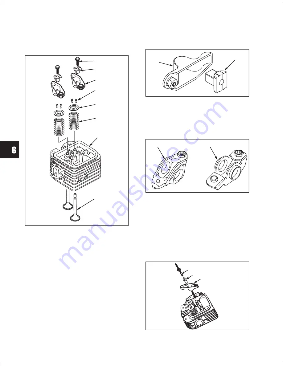
Fig.
1
shows the components of a typical V-Twin
OHV Cylinder Head.
Fig. 1
1. Screw
2. Rocker Arm Support
3. Rocker Arm
4. Valve Spring Retainer Locks
5. Valve Spring Retainer
6. Valve Spring
7. Cylinder Head
8. Valve
Rocker Arm Identification
Three different rocker arms have been used.
Style 3:
(Current) Engines manufactured after date
code 960331xx are equipped with a redesigned
cylinder head, and stamped steel rocker arms (1),
Fig. 2
, with a separate rocker arm support (2) for
each valve.
The redesigned cylinder head, gasket
and rocker arm assembly will not interchange with
previous cylinder heads. The new cylinder head may
be used on earlier V-Twins, but only as a complete
assembly. Refer to date code when ordering parts.
Fig. 2
Style 2:
Engines manufactured before 960401xx
but after 931031xx are equipped with cast aluminum
rocker arms (3) with a rocker arm shaft,
Fig. 3
.
Style 1:
Engines manufactured before date code
931101xx were equipped with stamped steel rocker
arms (4) with a rocker arm shaft,
Fig. 3
.
Fig. 3
CYLINDER HEAD SERVICE
Remove Cylinder Head
1. Remove two rocker studs (1) supports (2) and
rocker arm assemblies (3),
Fig. 4
(current) or
Fig. 5
(early). Remove rocker arm shaft (4, early
versions).
2. Remove push rods.
NOTE:
Label push rods for reassembly in the
original location.
Fig. 4
Содержание OHV V-Twin
Страница 27: ...1 26...
Страница 113: ...4 112...
Страница 156: ...10 155 Section 10 Crankshafts and Camshafts Page INSPECT CAMSHAFT 156 INSPECT CRANKSHAFT 156 INSPECT FLYWHEEL 157...
Страница 159: ...10 158...
Страница 177: ...12 176...


