22
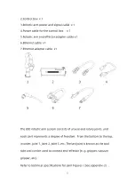
2.Control box x 1
3.Robotic arm power and signal cable x 1
4.Power cable for the control box x 1
5.Robotic arm end effector adapter cable x1
6.Ethernet cable x1
7.Ethernet adapter cable x1
The 850 robotic arm system consists of a base and rotary joints, and
each joint represents a degree of freedom. From the bottom to the top,
in order, Joint 1, Joint 2, Joint 3, etc. The last joint is known as the tool
side and can be used to connect end-effector (e. g. gripper, vacuum
gripper, etc).
Refer to technical specifications for joint Figures(See appendix-2).
Содержание 850
Страница 1: ...1...
Страница 72: ...72 4 The control box PC and network switch are connected by Ethernet ca ble...
Страница 74: ...74 Step3 Open the Properties Step4 Open the IPV4...
Страница 89: ...89 Cancel Cancel the selection Save Save the modified data Discard Discard the modified data...
Страница 145: ...145 1 6 6 GPIO Control Box and End tool interface...
Страница 149: ...149 1 6 7 End Effector...
Страница 197: ...197 State 6 Stop Generally use studio will generate state 6 and state 6 is also a kind of stop...


