−
User interface:
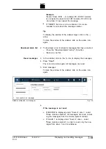
Set the following in the "DC Current Settings" area:
"Maximum Battery Charge Current [A]": maximum battery
charging current.
"Maximum Battery Discharge Current [A]": maximum bat-
tery discharging current
−
Modbus:
5. Enter limit values for the power output/power draw.
−
User interface:
Set the following in the "DC Power Settings" area:
"Maximum Terminal Power [W]": maximum power.
−
Modbus:
6. Enter current-voltage characteristic curve
.
−
User interface:
Set the following in the "Voltage Current Characteristics
(VCC) Settings" area:
"VCC Start Point Current [A]": battery current at mini-
mum battery voltage.
"VCC End Point Current [A]": battery current upon reach-
ing "VCC End Point Voltage [V]".
"VCC End Point Voltage [V]": battery voltage.
−
Modbus:
The charging and discharging current of a battery are set as
a function of the voltage with the "VCC-Settings". The val-
ues must be selected so that they lie in the shaded part of
the VCC curve.
The dashed line shows the "VCC-Settings" on delivery
(default values).
VCC curve
Fig. 7-12
A67-0140-00.BKen-0
01-05
2020-07-01
Process set values
7
‐
27
Содержание TruConvert DC 1000 Series
Страница 1: ...Operator s manual TruConvert DC series 1000 TruConvert System Control TruConvert Modular...
Страница 2: ......
Страница 6: ...II Good to know 2020 07 01 A67 0140 00 BKen 0 01 05...
Страница 36: ...3 12 Technical data dependent on device variant overview 2020 07 01 A67 0140 00 BKen 0 01 05...
Страница 38: ...7 Ethernet 4 10 8 RS 485 4 11 4 2 Interfaces 2020 07 01 A67 0140 00 BKen 0 01 05...
Страница 40: ...Fig 4 3 4 4 Protective earth TruConvert DC series 1000 2020 07 01 A67 0140 00 BKen 0 01 05...
Страница 48: ...4 12 RS 485 2020 07 01 A67 0140 00 BKen 0 01 05...
Страница 54: ...5 6 CSA certification 2020 07 01 A67 0140 00 BKen 0 01 05...
Страница 106: ...16 State diagram State machine Fig 7 19 7 38 State diagram 2020 07 01 A67 0140 00 BKen 0 01 05...


