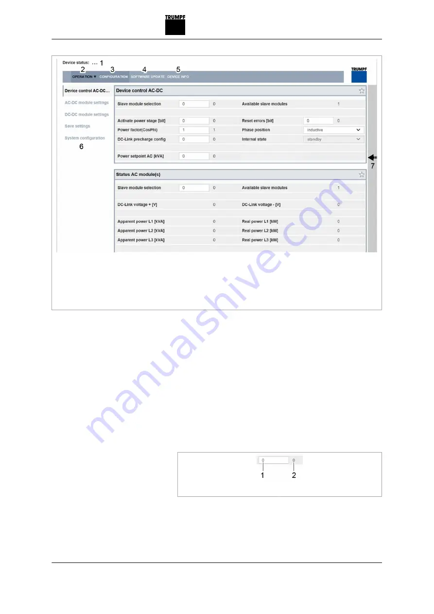
1
Display of the current device
status
2
Main operating parameters
(start page)
3
Device configuration (time and
network settings)
4
Software update
5
Device identification (display
only)
6
Submenu
7
Sidebar (alarm, warning and
event messages)
Start screen
Fig. 7-2
The system control balances the set system configuration
with the actually connected modules. If both values match,
the start screen of the web-based user interface is displayed.
If the set system configuration ("Expected Configuration") dif-
fers from the automatically detected system configuration
("Detected Configuration"), the initial commissioning screen
is displayed again and a message output. Press sidebar (7)
to display the messages.
12. Select >
Operation
>
DC Settings
.
13. Every input in the following steps must be confirmed with
the enter key
↲
.
1
Input field
2
Value applied in the system
Confirm input
Fig. 7-3
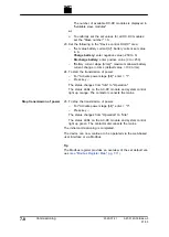
The value applied in the system is then displayed to the
right next to the input field.
14. Either
A67-0140-00.BKen-0
01-05
2020-07-01
Commissioning
7
‐
5
Setting process set values
(DC settings)
Содержание TruConvert DC 1000 Series
Страница 1: ...Operator s manual TruConvert DC series 1000 TruConvert System Control TruConvert Modular...
Страница 2: ......
Страница 6: ...II Good to know 2020 07 01 A67 0140 00 BKen 0 01 05...
Страница 36: ...3 12 Technical data dependent on device variant overview 2020 07 01 A67 0140 00 BKen 0 01 05...
Страница 38: ...7 Ethernet 4 10 8 RS 485 4 11 4 2 Interfaces 2020 07 01 A67 0140 00 BKen 0 01 05...
Страница 40: ...Fig 4 3 4 4 Protective earth TruConvert DC series 1000 2020 07 01 A67 0140 00 BKen 0 01 05...
Страница 48: ...4 12 RS 485 2020 07 01 A67 0140 00 BKen 0 01 05...
Страница 54: ...5 6 CSA certification 2020 07 01 A67 0140 00 BKen 0 01 05...
Страница 106: ...16 State diagram State machine Fig 7 19 7 38 State diagram 2020 07 01 A67 0140 00 BKen 0 01 05...


