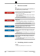
Connection cables carry life-threatening voltage.
Ø
Do not work under voltage.
Ø
Before connecting, check DC link voltage cables to ensure
that they are not electrically live.
10. Connect DC link voltage cables to the "DC Link" interface.
or
Ø
During parallel operation of several DC-DC modules:
Connect "DC Link" interfaces of the DC-DC modules in
parallel and connect DC link voltage cables.
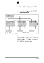
11. Connect data connection "RS-485" of the TruConvert Sys-
tem Control with data input "IN" of the DC-DC module.
12. Connect the terminating resistor to the "OUT" data output of
the DC-DC module.
or
Ø
If several DC-DC modules are connected in parallel: Con-
nect the "OUT" data output of the DC-DC module to the
"IN" data input of the next DC-DC module.
Connect the terminating resistor to the "OUT" data out-
put of the last DC-DC module.
13. Connect the TruConvert System Control to the master (Mod-
bus master or PC with web browser)
1
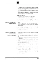
Cable for 24 V supply (2-
stranded)
2
Ferrite core
Ferrite core
Fig. 6-4
14. To satisfy EMC requirement C1, equip the cables for the 24
V supply of the DC-DC module and the system control with
the provided ferrite cores:
−
Wrap the cable once around the ferrite core.
−
Position the ferrite core as closely as possible to the
male connector.
15. Connect supply voltage 24 VDC to the DC-DC module.
16. Connect the 24 VDC supply voltage to the TruConvert Sys-
tem Control.
6
‐
10
Electrical connection
2020-07-01
A67-0140-00.BKen-0
01-05
Connecting DC link
DANGER
Connecting data cable
Connect 24 V supply voltage
Содержание TruConvert DC 1000 Series
Страница 1: ...Operator s manual TruConvert DC series 1000 TruConvert System Control TruConvert Modular...
Страница 2: ......
Страница 6: ...II Good to know 2020 07 01 A67 0140 00 BKen 0 01 05...
Страница 36: ...3 12 Technical data dependent on device variant overview 2020 07 01 A67 0140 00 BKen 0 01 05...
Страница 38: ...7 Ethernet 4 10 8 RS 485 4 11 4 2 Interfaces 2020 07 01 A67 0140 00 BKen 0 01 05...
Страница 40: ...Fig 4 3 4 4 Protective earth TruConvert DC series 1000 2020 07 01 A67 0140 00 BKen 0 01 05...
Страница 48: ...4 12 RS 485 2020 07 01 A67 0140 00 BKen 0 01 05...
Страница 54: ...5 6 CSA certification 2020 07 01 A67 0140 00 BKen 0 01 05...
Страница 106: ...16 State diagram State machine Fig 7 19 7 38 State diagram 2020 07 01 A67 0140 00 BKen 0 01 05...


