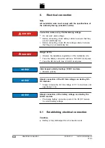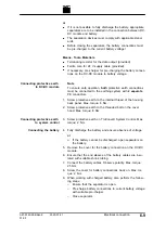
LED1 (green) flashes and shows that the DC-DC module is
operational
(see "Display elements", pg. 2
.
6.2
Connection diagram with 3 DC-DC
modules (example)
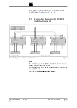
1
DC link voltage
2
Terminating resistor
Connection diagram: example with 3 DC-DC modules
Fig. 6-5
Note
The terminating resistor
must
be connected to the last bus par-
ticipant to ensure data transmission.
The terminating resistor must be connected even if there is only
one bus participant.
Use only the
provided terminating resistor
.
A67-0140-00.BKen-0
01-05
2020-07-01
Electrical connection
6
‐
11
Содержание TruConvert DC 1000 Series
Страница 1: ...Operator s manual TruConvert DC series 1000 TruConvert System Control TruConvert Modular...
Страница 2: ......
Страница 6: ...II Good to know 2020 07 01 A67 0140 00 BKen 0 01 05...
Страница 36: ...3 12 Technical data dependent on device variant overview 2020 07 01 A67 0140 00 BKen 0 01 05...
Страница 38: ...7 Ethernet 4 10 8 RS 485 4 11 4 2 Interfaces 2020 07 01 A67 0140 00 BKen 0 01 05...
Страница 40: ...Fig 4 3 4 4 Protective earth TruConvert DC series 1000 2020 07 01 A67 0140 00 BKen 0 01 05...
Страница 48: ...4 12 RS 485 2020 07 01 A67 0140 00 BKen 0 01 05...
Страница 54: ...5 6 CSA certification 2020 07 01 A67 0140 00 BKen 0 01 05...
Страница 106: ...16 State diagram State machine Fig 7 19 7 38 State diagram 2020 07 01 A67 0140 00 BKen 0 01 05...


