background image

The following drawings give the mechanical dimensions. All dimensions are in mm.

The following drawings give the mechanical dimensions. All dimensions are in mm.

Illustration 

Illustration  5. 1: TR1 2803-

5. 1: TR1 2803-2815 200-24

2815 200-240

0

Volt / TR1 

Volt / TR1 2805-2815 380-48

2805-2815 380-480 Volt

0 Volt

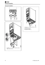
Illustration 

Illustration  5. 2: TR1 281

5. 2: TR1 2811ET, 200-240 

1ET, 200-240 Volt

Volt

TR1 2822, 200-240 Volt

TR1 2822, 200-240 Volt

TR1 2811ET, 380-480 Volt

TR1 2811ET, 380-480 Volt

TR1 2822-2840 380-480 Volt

TR1 2822-2840 380-480 Volt

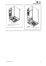
Illustration 

Illustration  5. 3: TR1 28

5. 3: TR1 2840 200-240 V

40 200-240 Volt

olt

TR1 2855-2875 380-480 Volt

TR1 2855-2875 380-480 Volt

Illustration 

Illustration  5. 4: TR1 2880

5. 4: TR1 2880-82 380-480 

-82 380-480 Volt

Volt

T

TR

R1


1


2

28

80

00


0


S

Se

erriie

es


s


V

VF

FD

D

8

83

3

Mechanical Dimensions

Mechanical Dimensions

Mechanical Installation

Mechanical Installation

Содержание VarioTrane TR1 2800 Series

Страница 1: ...TR1SVX15A EN TR1SVX15A EN Operating Instructions Operating Instructions VarioTrane TR1 Series 2800 VarioTrane TR1 Series 2800 TR1SV X15A EN TR1SV X15A EN June 2009 June 2009...

Страница 2: ...T TR R1 1 2 28 80 00 0 S Se er ri ie es s V VF FD D 1 1...

Страница 3: ...2 2 T TR R1 1 2 28 80 00 0 S Se er ri ie es s V VF FD D...

Страница 4: ...TR1 2800 Series VFD 3...

Страница 5: ...uations that could result in personal injury while notices indicate a situation that could result in equipment or property damage only accidents Your personal safety and the proper operation of this m...

Страница 6: ...28 Motor Thermal Protection If this function is desired set par 128 Motor Thermal Protection to data value ETR trip default value or data value ETR warning Note The function is initialized at 1 16 x r...

Страница 7: ...6 TR1 2800 Series VFD...

Страница 8: ...applications might also affect the electrical ratings Consult the relevant sections in this manual and in the for information about the electrical ratings Installation requirements The overall electr...

Страница 9: ...re version 1 00x The software version number can be seen from par 640 Software Version Equipment containing electrical components must not be disposed of together with domestic waste It must be separa...

Страница 10: ...here must be 10 cm free air passage above and below the frequency converter Drill holes in accordance with the measurements given in section Mechanical dimensions Retighten all four screws Fit the dec...

Страница 11: ...es is saved automatically after a mains failure If the display shows three dots at the right the parameter value has more than three digits In order to see the value activate CHANGE DATA Press QUICK M...

Страница 12: ...ed by adjusting the Local reference Local reference Parameter 003 Press Start to start the motor Set the motor speed by adjusting parameter 003 Local reference Check whether the direction of rotation...

Страница 13: ...er value is not to be implemented See also QUICK MENU CHANGE DATA is used for changing a setting The CHANGE DATA key is also used for confirming a change of parameter settings are used for selecting p...

Страница 14: ...tput frequency fout x p008 In order to enter the Menu mode QUICK MENU must be activated at the same time In Menu mode most of the frequency converter pa rameters can be changed Scroll through the para...

Страница 15: ...rst pressing CHANGE DATA and then changing the pa rameter value with the keys The Quick menu parameters are Par 100 Configuration Par 101 Torque characteristic Par 102 Motor power PM N Par 103 Motor v...

Страница 16: ...eset and Coasting Stop Inverse Quick Stop Inverse Stop Inverse Reversing DC Braking Inverse Setup Select LSB Setup Select MSB Thermistor Precise Stop Inverse Precise Stop Start Jog Stop Command Via Se...

Страница 17: ...tivated by pressing start 107 will now flash and dashes will move from left to right in the data value field 3 When 107 appears once more with the data value 0 AMT is complete Press STOP RESET to save...

Страница 18: ...TART key This cannot however override stop commands via the digital inputs see pa rameter 013 Local control 2 the STOP RESET and JOG keys on the condi tion that these are active 3 the FWD REV key on t...

Страница 19: ...tup 2 2 while the active Setup is set to Setup 1 1 in parameter 004 Active Setup Description of choice Factory Setup 0 contains the factory set data and can be used as a source of data if the other Se...

Страница 20: ...Value No readout none 0 Resulting reference reference 1 Resulting reference unit reference unit 2 Feedback unit feedback unit 3 Frequency Hz Frequency Hz 4 Output frequency x scaling frequency x scal...

Страница 21: ...communication in the range from Minimum reference RefMIN to Maximum reference RefMAX Status word Hex gives one or several status condi tions in a Hex code Heatsink temp C gives the present heatsink te...

Страница 22: ...from Remote operation to Local operation in parameter 002 Local remote operation while this pa rameter has been set to Remote operated control and open loop 1 The present motor frequency and di rectio...

Страница 23: ...engaged This function can only be active if Local operation 1 has been selected in pa rameter 002 Local remote operation Description of choice Auto restart use saved ref 0 is selected if the adjust a...

Страница 24: ...arameter can only be set using an LCP 2 control panel See Order form Description of choice The Quick Menu is set up as follows 1 Select parameter 025 Quick Menu setup and press CHANGE DATA 2 Index 1 i...

Страница 25: ...if a Devi ceNet card is mounted and Instance 20 70 or 21 71 is chosen in parameter 904 Instance types 101 Torque characteristic Value Constant torque Constant torque 1 Variable torque low torque low 2...

Страница 26: ...motor is star connected Y or delta connected 106 Rated motor speed Value 100 fM N x 60 max 60000 rpm 1140 Function This is where to set the value that corresponds to the rated motor speed nM N that ca...

Страница 27: ...ated by the motor supplier 3 The value is obtained through manual measure ments RS can be calculated by measuring the resistance RPHASE PHASE between two phase terminals Where RPHASE PHASE is lower th...

Страница 28: ...unction This is where to choose the required mode during the start delay time parameter 120 Start delay time Description of choice Select DC hold during start delay time 0 to energize the motor with a...

Страница 29: ...frequency will jump to the value in parameter 123 without ramping up This may cause an overcurrent warning alarm 126 DC brake time Value 0 60 sec 0 sec Function In this parameter the DC brake time is...

Страница 30: ...quency It is a precondition that parameter 121 Start function is set to Start fre quency voltage clockwise 3 or Start frequency voltage in reference direction 4 and that in parameter 120 Start delay a...

Страница 31: ...o ensure correct energizing of the motor and thus optimum dynamics accuracy and efficiency The U f ratio only affects the voltage characteristic if a selection has been made of Constant torque 1 pa ra...

Страница 32: ...2 Leakage reactance XL Value 0 000 XXX XXX Depends on choice of mo tor XL is sum of rotor and stator leakage reactance Function After setting of parameters 102 106 Nameplate data a number of adjustmen...

Страница 33: ...d this corresponds to the AC brake being inactive Please note 146 Reset voltage vector Value Off OFF 0 Reset RESET 1 Function When the voltage vector is reset it is set to the same starting point each...

Страница 34: ...at which the motor is allowed to run If Both directions has been selected in parameter 200 Output frequency range the minimum frequency is of no sig nificance Description of choice The value chosen c...

Страница 35: ...he highest value that can be assumed by the sum of all references If Closed loop 1 3 is selected in parameter 100 Configuration the maximum reference cannot exceed the value in parameter 415 Maximum f...

Страница 36: ...00 00 sec 10 00 sec Function The quick stop ramp down time is the deceleration time from the rated motor frequency to 0 Hz provided no overvoltage arises in the inverter because of gen erating operati...

Страница 37: ...to be the op tions 219 Catch up Slow down reference Value 0 00 100 of the given reference 0 00 Function In this parameter the percentage value can be set which will either be added to or deducted fro...

Страница 38: ...Warning Low frequency fLOW Value 0 0 par 226 Warn High frequency fHIGH 0 0 Hz Function If the output frequency falls below the preset limit fLOW a warning is given Parameters 223 228 Warning functions...

Страница 39: ...ns are activated when the output frequency has reached the resulting reference The signal outputs can be programmed to give a warning signal via ter minal 46 and via the relay output The unit for feed...

Страница 40: ...ise stop inverse PRECISE STOP INV 26 26 Precise start stop PRECISE START STOP 27 27 Pulse reference PULSE REFERENCE 28 Pulse feedback PULSE FEEDBACK 29 Pulse input PULSE INPUT 30 Selection of Setup ls...

Страница 41: ...Output frequency range direction Start clockwise is used if you want the motor shaft only to be able to rotate clockwise when started Should not be used for Process regulation closed loop Start anticl...

Страница 42: ...hermistor trip 2 and the thermistor is to be connected between a digital input and terminal 50 10 V supply Precise stop inverse is selected to obtain a high degree of accuracy when a stop command is r...

Страница 43: ...eter 317 used parameter 317 Time out Time out and 318 and 318 Function after Function after time out time out the value set must be higher than 1 Volt the value set must be higher than 1 Volt 3 31 10...

Страница 44: ...meter 317 317 Time out Time out If a time out function occurs at the If a time out function occurs at the same time as a same time as a bus time out function parameter 513 bus time out function parame...

Страница 45: ...k higher than FB Feedback higher than FBLOW LOW par 227 par 227 a ab bo ov ve e f fe ee ed db ba ac ck k l lo ow w 1 15 5 Feedback lower than FB Feedback lower than FBHIGH HIGH par 228 par 228 u un nd...

Страница 46: ...nction This parameter is used for setting the signal value that corresponds to the maximum value set in pa rameter 205 Maximum reference RefMAX or to the maximum feedback value set in parameter 415 Ma...

Страница 47: ...rmal ramp down time parameter 208 The counter function is activated starts timing at the flank of the start signal when it changes from stop to start Speed compensated stop To stop at precisely the sa...

Страница 48: ...ically Furthermore it is possi ble to select the number of times a restart is to be attempted The time between each attempt is set in parameter 406 Automatic restart time Description of choice If Manu...

Страница 49: ...the switching frequency is changed to 4 5 kHz 413 Overmodulation function Value Off off 0 On on 1 Function This parameter allows connection of the overmodu lation function for the output voltage Desc...

Страница 50: ...ion but if the amplification is too high the process may be come unstable in the case of overshooting 418 Speed PID integral time Value 20 00 999 99 ms 1000 OFF 100 ms Function The integral time deter...

Страница 51: ...by the lowpass filter 423 U1 voltage Value 0 0 999 0 V par 103 Function Parameters 423 428 are used when in parameter 101 Torque characteristic a selection has been made of Special motor characteristi...

Страница 52: ...e volt age limit or the max min frequency has been reached The process regulator will not engage again until either the error is zero or its sign has changed Select Disable 0 if the integrator is to c...

Страница 53: ...nal Description of choice Select the required time constant t If a time con stant t of 0 1 s is programmed the cut off frequency for the lowpass filter will be 1 0 1 10 RAD sec cor responding to 10 2...

Страница 54: ...d the speed variations will be less during initial tuning 456 Brake Voltage Reduce Value 0 25 V if 200V device 0 0 50 V if 400V device 0 Function The user sets the voltage by which the level for re si...

Страница 55: ...slave s response time is a maximum of 50 ms Only a slave that has received an error free telegram addressed to that slave can send a response telegram Broadcast A master can send the same telegram sim...

Страница 56: ...When the master has completed the telegram the slave s response time back to the master will be a maximum of 20 ms and there will be pause of at least 2 characters Pause time min 2 characters Respons...

Страница 57: ...7 1 address format 1 126 active Bit 0 6 Frequency converter address 1 126 Bit 0 6 0 Broadcast The slave sends the address byte back unchanged in the response telegram to the master Example writing to...

Страница 58: ...block usedto transfer parameters be tween master and slave The data block is made up of 12 bytes 6 words and also contains the process block The process block is made up of a data block of four bytes...

Страница 59: ...rd 0 1 1 1 Command cannot be performed 1 1 1 1 Text transferred If the command cannot be performed the slave sends this response 0111 Command cannot be performed and gives the following fault report i...

Страница 60: ...a parameter value write the new value is written in the PWE block and sent to the slave If the slave responds to a parameter request read command the present parameter value in the PWE block is transf...

Страница 61: ...h limit fMAX to be changed to 100 Hz The value must be recalled after a mains failure so it is written in EEPROM PKE E0CA Hex Write for parameter 202 Output frequency high limit fMAX IND 0000 Hex PWEH...

Страница 62: ...ributes of each parameter are displayed As a pa rameter value can only be transferred as a whole number a conversion factor must be used to transfer decimals Example Parameter 201 Output frequency low...

Страница 63: ...b 02 DC braking 03 Coasting stop 04 Quick stop 05 Freeze outp freq 06 Ramp stop Start 07 Reset 08 Jog 09 Ramp 1 Ramp 2 10 Data not valid Data valid 11 No function Relay 01 activated 12 No function Dig...

Страница 64: ...have been fulfilled Note In parameter 505 Start a se lection is made to define how Bit 06 Ramp stop start gates with the corresponding function on a digital in put Bit 07 Reset Bit 07 0 does not caus...

Страница 65: ...reversing Bit 15 1 causes reversing Note In the factory setting reversing is set to digital in parameter 506 Reversing Bit 15 only causes revers ing when either Ser communication Logic or or Logic and...

Страница 66: ...eration to be reestablished Bit 04 Not used Bit 04 is not used in the status word Bit 05 Not used Bit 05 is not used in the status word Bit 06 Trip lock Bit 06 0 means that the frequency converter is...

Страница 67: ...t there are no voltage warnings Bit 13 1 means that the DC voltage in the frequency converter s intermediate circuit is too low or too high Bit 14 Current limit Bit 14 0 means that the output current...

Страница 68: ...iption under Control word according to FC protocol Bit 06 Ramp stop start See description under Control word according to FC protocol Bit 07 Reset See description under Control word according to FC pr...

Страница 69: ...n under Status word according to FC pro tocol Bit 04 ON 2 OFF 2 Bit 04 0 means that Bit 01 in the control word 1 Bit 04 1 means that Bit 01 in the control word 0 Bit 05 ON 3 OFF 3 Bit 05 0 means that...

Страница 70: ...Control word and serial communication ref The frequency converter is to receive a start com mand and the reference is to be set to 50 2000 Hex of the reference range Control word 047F Hex Start comma...

Страница 71: ...201 Output frequency low limit Par 202 Output frequency high limit Example Status word and current output frequency The master receives a status message from the fre quency converter that the current...

Страница 72: ...ed of the master Parameter 501 Baudrate cannot be selected via the serial port but must be preset via the operating unit 502 Coasting Stop Value Digital input DIGITAL INPUT 0 Serial port SERIAL PORT 1...

Страница 73: ...ction 0 0 Quick stop 0 1 Quick stop 1 0 Quick stop 1 1 Motor running 504 DC brake Value Digital input DIGITAL INPUT 0 Serial port SERIAL PORT 1 Logic and LOGIC AND 2 Logic or LOGIC OR 3 Function See f...

Страница 74: ...ion 0 0 Stop 0 1 Start 1 0 Start 1 1 Start 506 Reversing Value Digital input DIGITAL INPUT 0 Serial port SERIAL PORT 1 Logic and LOGIC AND 2 Logic or LOGIC OR 3 Function See function description for p...

Страница 75: ...1 0 1 Setup 2 1 0 Setup 3 1 1 Setup 4 Serial communication 1 Setup msb Setup lsb Function 0 0 Setup 1 0 1 Setup 2 1 0 Setup 3 1 1 Setup 4 Logic and 2 Bus Set up msb Bus Set up lsb Dig Set up msb Dig S...

Страница 76: ...oice Select the desired control word profile 513 Bus time interval Value 1 99 sec 1 sec Function In this parameter it is possible to preset the maximum time expected to elapse between receipt of two c...

Страница 77: ...l unit Description of choice Resulting reference parameter 515 Gives the resulting reference as a percentage in the range from Minimum reference RefMIN to Maxi mum reference RefMAX See also Dealing wi...

Страница 78: ...n the frequency converter See Warning word extended status word and alarm word Control word parameter 539 Gives the present control word on the frequency con verter in Hex Warning word parameter 540 S...

Страница 79: ...and Modbus RTU see MG10SXYY 580 582Defined parameters Value Read only Function The three parameters hold a list of all the parameters that are defined in the TR1 2800 Series VFD It is pos sible to re...

Страница 80: ...equency converter undertaken on the frequency converter Parameter 604 Number of Parameter 604 Number of overtemperatures overtemperatures Gives the number of overtemperature faults that Gives the numb...

Страница 81: ...00 Setups with the exception of parameters 500 Ad Ad dress dress 501 501 Baudrate Baudrate 600 605 600 605 Operating data Operating data and and 615 617 615 617 Fault log Fault log Description of choi...

Страница 82: ...V 1 00 Example V 1 00 Parameter 625 Nameplate LCP 2 ID number Parameter 625 Nameplate LCP 2 ID number The ID number of the unit s LCP 2 appears here The ID number of the unit s LCP 2 appears here Exam...

Страница 83: ...uitable for remote mounting not suitable for remote mounting In some countries e g in the USA units with enclosure NEMA In some countries e g in the USA units with enclosure NEMA 1 are approved for re...

Страница 84: ...lustration Illustration 5 2 TR1 281 5 2 TR1 2811ET 200 240 1ET 200 240 Volt Volt TR1 2822 200 240 Volt TR1 2822 200 240 Volt TR1 2811ET 380 480 Volt TR1 2811ET 380 480 Volt TR1 2822 2840 380 480 Volt...

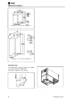
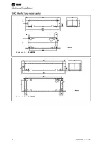
Страница 85: ...n 5 5 Motor Coils 195N3110 Illustration 5 6 RFI 1B filter 195N3103 The drawing below gives the dimensions for NEMA 1 terminal covers for TR1 2803 2875 Dimension a depends on the unit type 84 TR1 2800...

Страница 86: ...47 80 170 TR 2811ET 200 240 V TR 2811ET 380 480 V 195N2119 47 95 170 TR 2822 200 240 V TR2822 2840 380 480 V 195N2119 47 95 170 TR1 2840 200 240 V TR1 2855 2875 380 480 V 195N2120 47 145 170 TR1 2880...

Страница 87: ...Illustration 5 7 192H4719 Illustration 5 8 192H4720 86 TR1 2800 Series VFD...

Страница 88: ...Illustration 5 9 192H4893 All units require a minimum of 100 mm air between other components and vents of the enclosure TR1 2800 Series VFD 87...

Страница 89: ...All TR1 2800 units can be installed side by side and in any position as the units do not require ventilation on the side 88 TR1 2800 Series VFD...

Страница 90: ...ckplate at the lowest possible impedance To achieve low impedance connect the drive to the backplate with the drive fastening bolts Remove all paint from the contact points RCD relays multiple protect...

Страница 91: ...A high voltage test can be performed by short circuiting terminals U V W L1 L2 and L3 and applying max 2160 V DC in 1 sec between this short circuit and terminal 95 90 TR1 2800 Series VFD...

Страница 92: ...se cable clamps instead It is important to ensure good electrical contact from the installation plate through the installation screws to the metal cabinet of the frequency converter Use starwashers an...

Страница 93: ...Illustration 6 1 TR1 2803 2815 200 240 V 2805 2815 380 480 V Illustration 6 2 TR 2811ET 200 240 V TR1 2822 200 240 V TR 2811ET 380 480 V 2822 2840 380 480 V 92 TR1 2800 Series VFD...

Страница 94: ...3 TR1 2840 200 240 V 2855 2875 380 480 V Illustration 6 4 TR1 2880 2882 380 480V Please note that the units will be supplied with two bottom plates one for metric glands and one for conduits TR1 2800...

Страница 95: ...Branch Circuit Protection Short circuit protection 94 TR1 2800 Series VFD...

Страница 96: ...D Z C C J D D Z R K 1 J D D Z R K 1 J D D Z C C J D D Z R K 1 J D D Z 2 8 0 5 2 8 2 0 K T S R 2 0 J K S 2 0 J J S 2 0 F N Q R 2 0 K T K R 2 0 L P C C 2 0 5 0 1 7 9 0 6 0 2 0 K L S R 2 0 A T M R 2 5 A...

Страница 97: ...to terminal 99 See Technical data for correct dimensioning of cable cross section All types of three phase asynchronous standard mo tors can be connected to a frequency converter Nor mally small motor...

Страница 98: ...cording to IEC 61800 3 NOTE The RFI switch disconnects the capacitors galvanically from ground The switch Mk9 placed next to terminal 96 should be removed to disconnect the RFI filter The RFI switch i...

Страница 99: ...nical data for correct dimensioning of motor cable cross section and length Always comply with na tional and local regulations on cable cross section NOTE If an unscreened unarmoured cable is used som...

Страница 100: ...as a good mechanical connection to terminal 95 the cable cross section must be at least 10 mm 2 or 2 rated earth wires that are terminated sep arately To increase safety you can install an RCD Residua...

Страница 101: ...trol in parameter 323 or 341 for applications with an electromagnetic brake When the output frequency exceeds the brake cut out value set in par 138 the brake is released if the motor current exceeds...

Страница 102: ...unit use the instructions for the unit in question In connection with very long control cables and ana logue signals in rare cases depending on the instal lation 50 60 Hz earth loops may occur because...

Страница 103: ...53 Analogue voltage input 0 10 V DC 60 Analogue current input 0 4 20 mA 671 5 V DC supply voltage to Profibus 68 691 RS 485 Serial communication 701 Frame for terminals 67 68 and 69 Normally this ter...

Страница 104: ...first or last unit in the bus SYSTEM switches 1 and 2 must be ON On the remaining fre quency converters switches 1 and 2 must be OFF Switches 3 and 4 are not applied Connection to terminals 68 70 or...

Страница 105: ...dition the jog frequency is activated via terminal 29 Par 302 Digital input Pulse start 8 Par 303 Digital input Stop inverted 6 Par 304 Digital input Coasting stop inverted 2 Par 305 Digital input Jog...

Страница 106: ...Connection of a 2 wire transmitter as feedback to ter minal 60 Par 314 Analog input Feedback 2 Par 315 Terminal 60 min scaling 4 mA Par 316 Terminal 60 max scaling 20 mA TR1 2800 Series VFD 105...

Страница 107: ...All about TR1 2800 Series VFD 106 TR1 2800 Series VFD...

Страница 108: ...t kW This message is shown if an attempt is made to change a parameter value while the motor is running Stop the motor to change the parameter value This message is shown if an LCP 2 control unit is f...

Страница 109: ...the fault disappears only the alarm will blink After a reset the frequency converter will be ready to start operation again No Description Warning Alarm Trip locked 2 Live zero error LIVE ZERO ERROR X...

Страница 110: ...overvoltag limit the inverter will trip after a set time The time depends on the device and is set at 5 10 sec An overvoltage in the UDC can occur when the motor frequency is reduced too quickly due...

Страница 111: ...al communication to the frequency converter The warning will only be active when 514 Bus timeout function is set to a value other than OFF If parameter 514 Bus timeout function is set to Stop and trip...

Страница 112: ...40 internal fault number 3 Calibration constant in EEPROM Alarm 41 internal fault number 4 Data values in EEPROM Alarm 42 internal fault number 5 Fault in motor parameter database Alarm 43 internal fa...

Страница 113: ...V VDC Undervoltage 215 215 410 410 Voltage warning low 230 230 440 440 Voltage warning high 385 400 765 800 Overvoltage 410 410 820 820 The voltages stated are the intermediate circuit voltage of the...

Страница 114: ...on fault 40000000 Switch mode warning 80000000 Heat sink temperature high Bit Hex Extended status words 000001 Ramping 000002 AMT running 000004 Start forw reverse 000008 Slow down 000010 Catch up 000...

Страница 115: ...erature facilitate possible chemical processes on the components of the frequency converter These chemical processes quickly impact and damage the electronics In these areas cabinet fitting with fresh...

Страница 116: ...he PELV requirements Circuits that are connected to control terminals 12 18 19 20 27 29 33 42 46 50 53 55 and 60 are galvanically connected to one another Serial communication connected to fieldbus is...

Страница 117: ...reened armoured Yes 20 m screened arm oured Yes 7 m screened arm oured No 400 V version with 1A 1B RFI filter Yes 50 m screened armoured Yes 50 m screened arm oured Yes 25 m screened arm oured No 200...

Страница 118: ...times 0 02 3600 sec Torque characteristics Starting torque parameter 101 Torque characteristic Constant torque 160 in 1 min Starting torque parameter 101 Torque characteristics Variable torque 160 in...

Страница 119: ...ic 1 10 V DC Maximum voltage on input 28 V DC Input resistance Ri approx 2 k Scan interval 13 3 msec Resolution 10 bit Accuracy 100 Hz 1 kHz terminal 33 Max error 0 5 of full scale Accuracy 1 kHz 67 6...

Страница 120: ...and inductive load 1 3 break 1 2 make Max terminal load AC1 on 1 3 1 2 control card 250 V AC 2 A 500 VA Max terminal load DC1 IEC 947 on 1 3 1 2 control card 25 V DC 2 A 50 V DC 1A 50W Min terminal lo...

Страница 121: ...full scale operation 0 C Min ambient temperature at reduced performance 10 C Temperature during storage transport 25 65 70 C Max altitude above sea level 1000 m EMC standards Emission EN 50081 2 EN 61...

Страница 122: ...es IEC UL2 A 20 20 20 20 20 20 20 20 20 20 20 20 25 25 Efficiency3 95 95 95 95 95 95 95 Power loss at 100 load W 24 35 48 69 94 125 231 Weight kg 2 0 2 0 2 0 3 7 2 0 2 0 6 0 Enclosure4 type IP 20 IP 2...

Страница 123: ...5 11 0 15 0 18 5 Typical shaft output PM N HP 5 0 7 5 10 0 15 0 20 0 25 0 Max cable cross sec tion motor mm2 AWG 1 4 10 4 10 4 10 16 6 16 6 16 6 Input current IL N A 8 1 10 6 14 9 24 0 32 0 37 5 3 x 3...

Страница 124: ...ot active Yes 0 5 016 Local reversing Not active Yes 0 5 017 Local reset of trip Active Yes 0 5 018 Data change lock Not locked Yes 0 5 019 Operating status at power up Auto Restart Yes 0 5 020 Lock f...

Страница 125: ...Coasting during start delay time Yes 0 5 122 Function at stop Coast Yes 0 5 123 Min freq for activation of par 122 0 1 Hz Yes 1 5 126 DC braking time 0 sec Yes 1 6 127 DC brake engaging frequency OFF...

Страница 126: ...10 00 sec Yes Yes 2 7 212 Quick stop ramp down time 10 00 sec Yes Yes 2 7 213 Jog frequency 10 0 Hz Yes Yes 1 6 214 Reference function External Preset Yes Yes 0 5 215 Preset reference 1 0 00 Yes Yes 2...

Страница 127: ...put 0 IMAX 0 20 mA Yes 0 5 323 Relay output Control ready Yes 0 5 327 Pulse ref FB 5000 Hz Yes 0 7 341 Term 46 digital output Control ready Yes 0 5 342 Term 46 Max pulse output 5000 Hz Yes 0 6 343 Pre...

Страница 128: ...1 6 427 U3 voltage par 103 Yes 1 6 428 F3 frequency par 104 Yes 1 6 437 Proc PID no inv Normal Yes 0 5 438 Proc PID anti wind Active Yes 0 5 439 Proc PID start frequency Par 201 Yes 1 6 440 Proc PID s...

Страница 129: ...ata readout Frequency x scaling No 1 3 520 Data readout Motor current No 2 7 521 Data readout Torque No 1 3 522 Data readout Power kW No 1 7 523 Data readout Power HP No 2 7 524 Data readout Motor vol...

Страница 130: ...Application option type No 0 9 630 Nameplate Communication option type No 0 9 632 Nameplate BMC software identification No 0 9 634 Nameplate Unit identification for communication No 0 9 635 Nameplate...

Страница 131: ...R 102 Motor Power 1 1 kW Based on motor 103 Motor Voltage For 200 V units 230 V For 400 V units 460 V Based on motor 105 Motor Current 2 7 A Based on motor 106 Rated Motor Speed 1140 RPM Based on moto...

Страница 132: ...60 Hz line power 50 Hz for 50 Hz line power 204 Minimum Reference 22 Hz 6 Hz for 60 Hz line power 5 Hz for 50 Hz line power 205 Maximum Reference 60 Hz 60 Hz for 60 Hz line power 50 Hz for 50 Hz line...

Страница 133: ...Keys 12 Control Panel 12 Control Terminals 100 102 Control Unit 12 Control Word 62 67 Counter Value 46 Current Limit 36 Current Minimum Value 31 Data Character byte 57 Data Readout 76 Dc Brake Time 28...

Страница 134: ...Test 90 High Voltage Warning 89 Initialise 80 Installation At High Altitudes 6 Ip 21 Solution 85 Jog Frequency 35 Jog Ramp Time 35 Language 17 Large Display Readout 19 Lcp Copy 19 Leakage Reactance 3...

Страница 135: ...12 Quick Menu Setup 23 Quick Menu Userdefined 23 Quick stop Ramp down Time 35 Ramp Type 34 Ramp down Time 35 Ramp up Time 34 Rated Motor Speed 25 Rcd 99 Rcd Relays 89 Reference Function 35 Reference...

Страница 136: ...am Profile 75 Telegram Structure 55 Telegram Traffic 54 Temperature dependent Switch Frequency 115 Terminal 42 43 Terminal 46 45 Terminal 53 42 Terminal 60 42 Terminal Cover 84 Terminals 104 Thermal M...

Страница 137: ...us at comfort trane com 195R2037 MG28L202 MG28L202 Trane has a policy of continous product and product data improvement and reserves the right to change design and speci cations without notice Literat...

Отзывы: