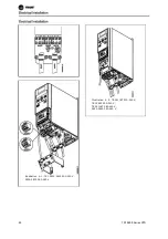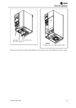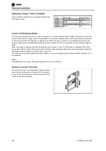
Control wires must be connected with a tightening torque of 0.22-0.25 Nm.
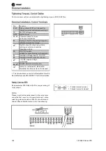
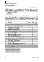
No.
Function
01-03
Relay outputs 01-03 can be used for
indicating status and alarms/warnings.
12
24 V DC voltage supply.
18-33
Digital inputs.
20, 55
Common frame for input
and output terminals.
42
Analog output for displaying frequency,
reference, current or torque.
461
Digital output for displaying status,
warnings or alarms, as well as
frequency output.
50
+10 V DC supply
voltage for potentiometer or thermistor.
53
Analogue voltage input 0 - 10 V DC.
60
Analogue current input 0/4 - 20 mA.
671
+ 5 V DC supply voltage
to Profibus.
68, 691 RS 485, Serial communication.
701
Frame for terminals 67, 68 and 69.
Normally this terminal is not to be used.
1. The terminals are not valid for DeviceNet. See the
DeviceNet manual, MG.90.BX.YY for further details.
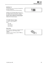
See parameter 323
Relay output
for programming of
relay output.
Nr. 01 - 02
1 - 2 make (normally open)
01 - 03
1 - 3 break (normally closed)
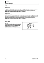
NOTE:
Please note that the cable jacket for the relay must
cover the first row of control card terminals - other-
wise the galvanic isolation (PELV) cannot be main-
tained. Max. cable diameter: 4 mm. See drawing.
102
TR1
2800
Series
VFD
Tightening Torques, Control Cables
Electrical Installation, Control Terminals
Relay Connection
Electrical Installation
Содержание VarioTrane TR1 2800 Series
Страница 2: ...T TR R1 1 2 28 80 00 0 S Se er ri ie es s V VF FD D 1 1...
Страница 3: ...2 2 T TR R1 1 2 28 80 00 0 S Se er ri ie es s V VF FD D...
Страница 4: ...TR1 2800 Series VFD 3...
Страница 7: ...6 TR1 2800 Series VFD...
Страница 87: ...Illustration 5 7 192H4719 Illustration 5 8 192H4720 86 TR1 2800 Series VFD...
Страница 95: ...Branch Circuit Protection Short circuit protection 94 TR1 2800 Series VFD...
Страница 107: ...All about TR1 2800 Series VFD 106 TR1 2800 Series VFD...


