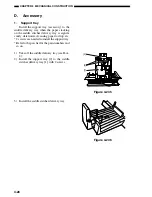
6-6
CHAPTER 6 TROUBLESHOOTING
11) Change the settings of bits 6 through 8 on
DIPSW1 referring to Table 8-102 below.
• If the width adjustment is “0”,
The stitching position and the folding po-
sition match, requiring no change.
• If for “positive width adjustment,”
Set DIPSW1 so that the difference result-
ing from subtraction of the interval from
the appropriate setting in Table 8-102 is
provided.
For instance, if the DIPSW1 is currently
set to +2 and the interval is +1 mm, set
DIPSW1 to reflect -2.
• If for “negative width adjustment”
Set DIPSW1 so that the sum resulting
from addition of the interval from the ap-
propriate setting is provided.
For instance, if the DIPSW1 is currently
set to -1 and the interval is +0.5 mm, set
DIPSW1 to r1.
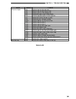
DIPSW1 bit settings
Settings
bit 6
bit 7
bit 8 (in units of 0.5 mm)
OFF
ON
ON
+3
OFF
ON
OFF
+2
OFF
OFF
ON
+1
OFF
OFF
OFF
0
ON
OFF
ON
−
1
ON
ON
OFF
−
2
ON
ON
ON
−
3
Do not touch the following:
bit 6
bit 7
bit 8
ON
OFF
OFF
Table 6-02
12) Set bits 1 through 4 on DIPSW1 to OFF.
2. Stitching Position (adjusting cen-
ter stitching)
Use the host machine adjustment mode
to perform the following:
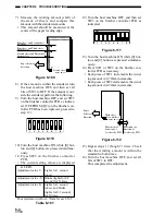
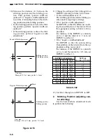
10) Measure the distance (L) between the
stitching position and the folding posi-
tion. Then, perform “positive width ad-
justment” or “negative width adjustment”
to suit the relationship between the stitch-
ing position and the folding position.
• If the stitching position is below the fold-
ing position, perform “positive width ad-
justment.”
• If the stitching position is above the fold-
ing position, perform “negative width
adjustment.”
Mark
Mark
Folding position
Stitching position
Stitching position
Folding position
Positive Width Adjustment
Negative Width Adjustment
Unit: mm
Example: If L is 1 mm, provide “+1 mm”.
Unit: mm
Example: If L is 0.5 mm, provide “-0.5 mm”.
Figure 6-6
Содержание MJ-1027
Страница 1: ...SERVICE MANUAL FINISHER MJ 1027 1028 File No SME040041A0 R04102169300 TTEC Ver01_2007 09 ...
Страница 5: ...ii ...
Страница 9: ...vi ...
Страница 70: ...2 41 CHAPTER 2 FINISHER UNIT BASIC OPERATION Height sensor PS1 Paper Figure 2 240 ...
Страница 101: ...3 15 CHAPTER 3 SADDLE STITCHER UNIT BASIC OPERATION Figure 3 301 ...
Страница 104: ...3 18 CHAPTER 3 SADDLE STITCHER UNIT BASIC OPERATION 2 A3 LD Paper Path 3 sheets Figure 3 303 ...
Страница 116: ...3 30 CHAPTER 3 SADDLE STITCHER UNIT BASIC OPERATION Cam Mount Figure 3 404 ...
Страница 150: ...4 20 CHAPTER 4 MECHANICAL CONSTRUCTION 7 Remove the tension springs front 5 rear 6 Figure 4 216 Figure 4 217 5 6 ...
Страница 173: ...6 CHAPTER 6 TROUBLESHOOTING II ARRANGEMENT OF ELECTRICAL PARTS A Finisher Unit ...
Страница 235: ...2 17 2 HIGASHIGOTANDA SHINAGAWA KU TOKYO 141 8664 JAPAN ...

