6-25
CHAPTER 6 TROUBLESHOOTING
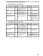
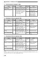
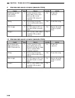
8.
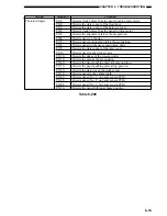
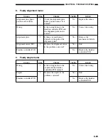
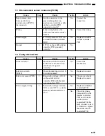
Faulty alignment motor
9.
Faulty staple motor
Checks
Is the wiring between the
stapler and the finisher
controller PCB normal?
Replace the stapler. Is the
problem corrected?
Cause
Wiring
Stapler
Finisher controller PCB
Step
1
2
Yes/No
No
Yes
No
Action
Correct the wiring.
End.
Replace the finisher
controller PCB.
Checks
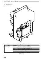
Check the alignment plate
home position sensor. Is it
normal?
Is the wiring between the
finisher controller PCB and
the alignment plate motor
normal?
Is there any mechanical
obstacle in the path of the
alignment plate?
Replace the alignment motor.
Is the problem corrected?
Cause
Alignment plate home
position sensor (PI6)
Wiring
Alignment plate
Alignment motor (M3)
Finisher controller PCB
Step
1
2
3
4
Yes/No
No
No
Yes
Yes
No
Action
Replace the sensor.
Correct the wiring.
Remove the
mechanical obstacle.
End.
Replace the finisher
controller PCB.
Содержание MJ-1027
Страница 1: ...SERVICE MANUAL FINISHER MJ 1027 1028 File No SME040041A0 R04102169300 TTEC Ver01_2007 09 ...
Страница 5: ...ii ...
Страница 9: ...vi ...
Страница 70: ...2 41 CHAPTER 2 FINISHER UNIT BASIC OPERATION Height sensor PS1 Paper Figure 2 240 ...
Страница 101: ...3 15 CHAPTER 3 SADDLE STITCHER UNIT BASIC OPERATION Figure 3 301 ...
Страница 104: ...3 18 CHAPTER 3 SADDLE STITCHER UNIT BASIC OPERATION 2 A3 LD Paper Path 3 sheets Figure 3 303 ...
Страница 116: ...3 30 CHAPTER 3 SADDLE STITCHER UNIT BASIC OPERATION Cam Mount Figure 3 404 ...
Страница 150: ...4 20 CHAPTER 4 MECHANICAL CONSTRUCTION 7 Remove the tension springs front 5 rear 6 Figure 4 216 Figure 4 217 5 6 ...
Страница 173: ...6 CHAPTER 6 TROUBLESHOOTING II ARRANGEMENT OF ELECTRICAL PARTS A Finisher Unit ...
Страница 235: ...2 17 2 HIGASHIGOTANDA SHINAGAWA KU TOKYO 141 8664 JAPAN ...

