3-28
CHAPTER 3 SADDLE STITCHER UNIT BASIC OPERATION
IV.
STITCHING SYSTEM
1.
Outline
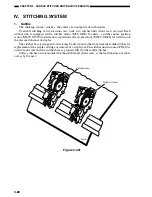
The stitching system “stitches” the center of an output stack with staples.
To enable stitching at two locations on a stack, two stitcher units (front, rear) are used. Each
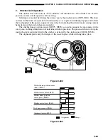
stitcher unit is equipped with a stitcher motor (M7S, M6S) for drive, a stitcher home position
sensor (MS7S, MS5S) for detection of position and a staple sensor (MS6S, MS4S) for detection of
the presence/absence of staples.
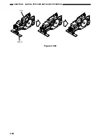
The stitcher base is designed so that it may be drawn out to the front from the saddle stitcher for
replacement of the staple cartridge or removal of a staple jam. The stitcher unit in sensor (PI16S) is
used to make sure that the stitcher base is properly fitted to the saddle stitcher.
Safety switches are not mounted for the stitcher unit (front, rear), as the location does not allow
access by the user.
Stitcher (rear)
Stitcher (front)
Stack
Figure 3-401
Содержание MJ-1027
Страница 1: ...SERVICE MANUAL FINISHER MJ 1027 1028 File No SME040041A0 R04102169300 TTEC Ver01_2007 09 ...
Страница 5: ...ii ...
Страница 9: ...vi ...
Страница 70: ...2 41 CHAPTER 2 FINISHER UNIT BASIC OPERATION Height sensor PS1 Paper Figure 2 240 ...
Страница 101: ...3 15 CHAPTER 3 SADDLE STITCHER UNIT BASIC OPERATION Figure 3 301 ...
Страница 104: ...3 18 CHAPTER 3 SADDLE STITCHER UNIT BASIC OPERATION 2 A3 LD Paper Path 3 sheets Figure 3 303 ...
Страница 116: ...3 30 CHAPTER 3 SADDLE STITCHER UNIT BASIC OPERATION Cam Mount Figure 3 404 ...
Страница 150: ...4 20 CHAPTER 4 MECHANICAL CONSTRUCTION 7 Remove the tension springs front 5 rear 6 Figure 4 216 Figure 4 217 5 6 ...
Страница 173: ...6 CHAPTER 6 TROUBLESHOOTING II ARRANGEMENT OF ELECTRICAL PARTS A Finisher Unit ...
Страница 235: ...2 17 2 HIGASHIGOTANDA SHINAGAWA KU TOKYO 141 8664 JAPAN ...


