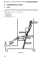
3-6
CHAPTER 3 SADDLE STITCHER UNIT BASIC OPERATION
4.
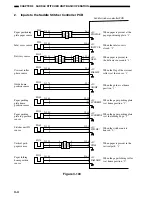
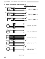
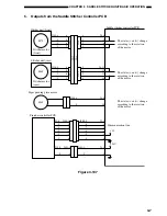
Outputs from the Saddle Stitcher Controller PCB
SL1S
J118
-1
-2
+24V
FLPSL1*
When “0”, the solenoid turns ON.
Saddle stitcher controller PCB
-2
J15-1
-2
-1
SL2S
J117
-1
-2
+24V
FLPSL2*
When “0”, the solenoid turns ON.
-2
J15-3
-4
-1
SL4S
J116
-1
-2
+24V
RLNIPSL*
When “0”, the solenoid turns ON.
-2
J15-5
-6
-1
-1
-4
-4
-1
-3
-2
-2
-3
+24V
The pulse signals change according
to the rotation of the motor.
J7-1
-2
A*
B*
-3
B
-4
A
-5
J113-5
-4
-3
-2
-1
M5S
The pulse signals change according
to the rotation of the motor.
J5-1
A*
A
-2
B
-3
B*
-4
M1S
+24V
The pulse signals change according
to the rotation of the motor.
J7-6
-7
A*
B*
-8
B
-9
A
-10
J114-5
-4
-3
-2
-1
M4S
+24V
The pulse signals change according
to the rotation of the motor.
J12-1
-2
A*
B*
-3
B
-4
A
-5
J119-5
-4
-3
-2
-1
M3S
The states (+ and -) change according
to the rotation of the motor.
J4-8
-7
J112-2
-1
M2S
J115A
No.1 paper deflecting plate solenoid
No.2 paper deflecting plate solenoid
Feed plate contact solenoid
Feed motor
Paper folding motor
Guide motor
Paper positioning plate motor
Alignment motor
Figure 3-106
Содержание MJ-1027
Страница 1: ...SERVICE MANUAL FINISHER MJ 1027 1028 File No SME040041A0 R04102169300 TTEC Ver01_2007 09 ...
Страница 5: ...ii ...
Страница 9: ...vi ...
Страница 70: ...2 41 CHAPTER 2 FINISHER UNIT BASIC OPERATION Height sensor PS1 Paper Figure 2 240 ...
Страница 101: ...3 15 CHAPTER 3 SADDLE STITCHER UNIT BASIC OPERATION Figure 3 301 ...
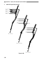
Страница 104: ...3 18 CHAPTER 3 SADDLE STITCHER UNIT BASIC OPERATION 2 A3 LD Paper Path 3 sheets Figure 3 303 ...
Страница 116: ...3 30 CHAPTER 3 SADDLE STITCHER UNIT BASIC OPERATION Cam Mount Figure 3 404 ...
Страница 150: ...4 20 CHAPTER 4 MECHANICAL CONSTRUCTION 7 Remove the tension springs front 5 rear 6 Figure 4 216 Figure 4 217 5 6 ...
Страница 173: ...6 CHAPTER 6 TROUBLESHOOTING II ARRANGEMENT OF ELECTRICAL PARTS A Finisher Unit ...
Страница 235: ...2 17 2 HIGASHIGOTANDA SHINAGAWA KU TOKYO 141 8664 JAPAN ...

