1-14
CHAPTER 1 GENERAL DESCRIPTION
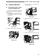
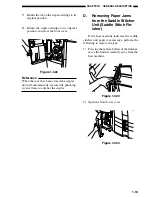
3) Turn the knob on the left side.
Figure 1-325
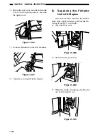
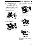
4) Turn the knob on the right side while push-
ing it in.
Figure 1-326
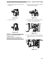
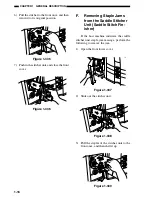
5) Remove the jam.
Figure 1-327
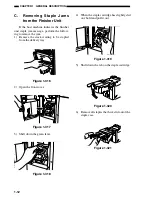
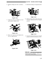
6) Open the inlet cover, and remove the jam.
Figure 1-328
7) Close the front lower cover.
Figure 1-329
8) Connect the finisher unit.
9) Operate as instructed on the display.
Содержание MJ-1027
Страница 1: ...SERVICE MANUAL FINISHER MJ 1027 1028 File No SME040041A0 R04102169300 TTEC Ver01_2007 09 ...
Страница 5: ...ii ...
Страница 9: ...vi ...
Страница 70: ...2 41 CHAPTER 2 FINISHER UNIT BASIC OPERATION Height sensor PS1 Paper Figure 2 240 ...
Страница 101: ...3 15 CHAPTER 3 SADDLE STITCHER UNIT BASIC OPERATION Figure 3 301 ...
Страница 104: ...3 18 CHAPTER 3 SADDLE STITCHER UNIT BASIC OPERATION 2 A3 LD Paper Path 3 sheets Figure 3 303 ...
Страница 116: ...3 30 CHAPTER 3 SADDLE STITCHER UNIT BASIC OPERATION Cam Mount Figure 3 404 ...
Страница 150: ...4 20 CHAPTER 4 MECHANICAL CONSTRUCTION 7 Remove the tension springs front 5 rear 6 Figure 4 216 Figure 4 217 5 6 ...
Страница 173: ...6 CHAPTER 6 TROUBLESHOOTING II ARRANGEMENT OF ELECTRICAL PARTS A Finisher Unit ...
Страница 235: ...2 17 2 HIGASHIGOTANDA SHINAGAWA KU TOKYO 141 8664 JAPAN ...

