2-38
CHAPTER 2 FINISHER UNIT BASIC OPERATION
G.
Tray Operation
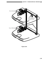
The finisher has two delivery trays. The upper tray is called tray-1 and lower tray is called
tray-2. The tray-1 and tray-2 move up and down independently.
Tray-1 is moved up and down by the tray-1 lift motor (M5), and tray-2 by the tray-2 lift motor
(M10).
The finisher controller PCB switches the motor driving direction of the tray lift motors (the
motor driver PCB embedded) to control the vertical movement of the trays. When the power is
turned ON, the finisher controller PCB drives the tray lift motors (M5/M10) to return the trays to
their home positions. If the tray is already at the home position, it is moved away from the home
position once, and then returned to that position. If both tray-1 and tray-2 are at the home position,
the above operation is performed for the tray-1 and -2 in this order.
The tray position is detected by the following operation:
The finisher controller PCB counts the clock signal outputted from the tray lift motor (the
motor driver PCB embedded) as soon as the tray starts to move. The finisher controller PCB moves
up and down the tray selected by the host machine so that it is positioned at the delivery slot.
The lower limit of the tray-1 is detected by the tray coming close detecting switch (MS 9). The
finisher controller PCB stops the drive (down) of the tray-1 lift motor (M5) as soon as the tray
coming close detection switch (MS9) turns on.
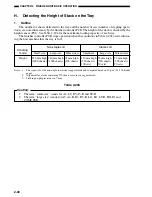
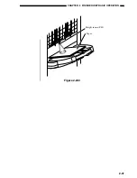
The height of the stack on the tray is identified by the height sensor (PS1), which measures its
distance from the top of the stack. The tray is moved down when the distance between the top of the
stack on the tray and the sensor becomes less than the specific measurement.
The finisher controller PCB cuts off the +24V power of the tray lift motors (M5/M10) as soon
as the safety zone switch (MS3) turns ON while the shutter and the swing guide are open, stopping
the operation of the finisher.
Содержание MJ-1027
Страница 1: ...SERVICE MANUAL FINISHER MJ 1027 1028 File No SME040041A0 R04102169300 TTEC Ver01_2007 09 ...
Страница 5: ...ii ...
Страница 9: ...vi ...
Страница 70: ...2 41 CHAPTER 2 FINISHER UNIT BASIC OPERATION Height sensor PS1 Paper Figure 2 240 ...
Страница 101: ...3 15 CHAPTER 3 SADDLE STITCHER UNIT BASIC OPERATION Figure 3 301 ...
Страница 104: ...3 18 CHAPTER 3 SADDLE STITCHER UNIT BASIC OPERATION 2 A3 LD Paper Path 3 sheets Figure 3 303 ...
Страница 116: ...3 30 CHAPTER 3 SADDLE STITCHER UNIT BASIC OPERATION Cam Mount Figure 3 404 ...
Страница 150: ...4 20 CHAPTER 4 MECHANICAL CONSTRUCTION 7 Remove the tension springs front 5 rear 6 Figure 4 216 Figure 4 217 5 6 ...
Страница 173: ...6 CHAPTER 6 TROUBLESHOOTING II ARRANGEMENT OF ELECTRICAL PARTS A Finisher Unit ...
Страница 235: ...2 17 2 HIGASHIGOTANDA SHINAGAWA KU TOKYO 141 8664 JAPAN ...

