4-11
CHAPTER 4 MECHANICAL CONSTRUCTION
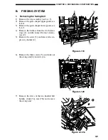
Figure 4-125
3.
Removing the Buffer Roller
Assembly
1) Remove the finisher controller PCB (see I-
C-1).
2) Remove the feed drive unit (see I-B-2).
3) Remove the screw [1], and remove the guide
support plate assembly [2] to slide out the
harness leads [3] towards the buffer roller
assembly side.
Figure 4-126
Caution:
Before re-attaching the removed feed drive
unit back on the finisher unit, loosen the move
gear stop screw [8] to relieve the tension, and
then fasten the screw after attaching the feed
drive unit.
The move gear attachment must be adjusted
also when removing and attaching the swing
unit.
If you forget to fasten the screw, the gear teeth
may disengage, resulting in defective feed.
[8]
[1]
[2]
[3]
4) Remove the three screws [6], and remove
the feed drive unit [7].
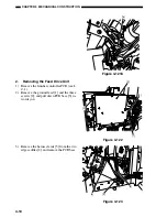
Figure 4-124
[6]
[6]
[6]
[7]
Содержание MJ-1027
Страница 1: ...SERVICE MANUAL FINISHER MJ 1027 1028 File No SME040041A0 R04102169300 TTEC Ver01_2007 09 ...
Страница 5: ...ii ...
Страница 9: ...vi ...
Страница 70: ...2 41 CHAPTER 2 FINISHER UNIT BASIC OPERATION Height sensor PS1 Paper Figure 2 240 ...
Страница 101: ...3 15 CHAPTER 3 SADDLE STITCHER UNIT BASIC OPERATION Figure 3 301 ...
Страница 104: ...3 18 CHAPTER 3 SADDLE STITCHER UNIT BASIC OPERATION 2 A3 LD Paper Path 3 sheets Figure 3 303 ...
Страница 116: ...3 30 CHAPTER 3 SADDLE STITCHER UNIT BASIC OPERATION Cam Mount Figure 3 404 ...
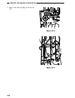
Страница 150: ...4 20 CHAPTER 4 MECHANICAL CONSTRUCTION 7 Remove the tension springs front 5 rear 6 Figure 4 216 Figure 4 217 5 6 ...
Страница 173: ...6 CHAPTER 6 TROUBLESHOOTING II ARRANGEMENT OF ELECTRICAL PARTS A Finisher Unit ...
Страница 235: ...2 17 2 HIGASHIGOTANDA SHINAGAWA KU TOKYO 141 8664 JAPAN ...


