background image

3-10

CHAPTER 3   SADDLE STITCHER UNIT BASIC OPERATION

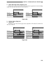
2.

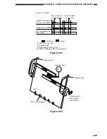
Aligning the Sheets

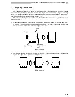
The alignment plates operate to put the sheets in order each time a sheet of paper is output to

the vertical path assembly. The alignment plates are mounted at the edge of the vertical path assem-
bly.

The alignment plates also operate after stapling to prepare the stack for delivery.

Sheets

Paper positioning plate

Alignment plate

Alignment plate

Figure 3-203

Содержание MJ-1027

Страница 1: ...SERVICE MANUAL FINISHER MJ 1027 1028 File No SME040041A0 R04102169300 TTEC Ver01_2007 09 ...

Страница 2: ...l or other related materials Be careful not to reassemble small parts such as screws washers pins E rings toothed washers to the wrong places 8 Basically the machine should not be operated with any parts removed or disassembled 9 Delicate parts for preventing safety hazard problems such as breakers thermofuses fuses door switches sensors etc if any should be handled installed adjusted cor rectly 1...

Страница 3: ...15 When you move the finisher do not move it in the direction of the arrow as shown in the figure below otherwise it might fall down 2005 TOSHIBA TEC CORPORATION ALL rights reserved ...

Страница 4: ...assembled assembled and adjusted Chapter 5 Maintenance and Inspection provides tables of periodically replaced parts and consumables and durables together with a scheduled servicing chart Chapter 6 Troubleshooting shows how to troubleshoot possible faults and gives electri cal parts arrangement diagrams LED check pin diagrams by PCB and self diagnosis tables Appendix contains diagrams showing tabl...

Страница 5: ...ii ...

Страница 6: ... Removing Staple Jams from the Saddle Stitcher Unit Saddle Stitch Finisher 1 16 IV MAINTENANCE BY THE USER 1 18 A Maintenance by the User 1 18 I BASIC OPERATION 2 1 A Outline 2 1 B Outline of Electrical Circuitry 2 2 C Inputs to and Outputs from the Finisher Controller PCB 2 4 II FEED DRIVE SYSTEM 2 10 A Outline 2 10 B Type of Delivery Paths 2 15 C Feeding and Delivering 2 18 D Job Offset 2 21 E S...

Страница 7: ...M 3 31 VI CHECKING FOR A JAM 3 38 VII POWER SUPPLY 3 43 CHAPTER 3 SADDLE STITCHER UNIT BASIC OPERATION CHAPTER 4 MECHANICAL CONSTRUCTION I FINISHER UNIT 4 1 A Externals and Controls 4 1 B FEEDING SYSTEM 4 9 C PCBs 4 13 II SADDLE STITCHER UNIT 4 14 A Externals and Controls 4 14 B SADDLE STITCHER UNIT 4 17 C PCBs 4 27 D Accessory 4 28 I PERIODICALLY REPLACED PARTS 5 1 A Finisher Unit 5 1 B Saddle St...

Страница 8: ...er Unit 6 7 B Saddle Stitcher Unit 6 14 C Light Emitting Diodes LED and Check Pins by PCB 6 20 III TROUBLESHOOTING 6 22 A Finisher Unit 6 22 B Saddle Stitcher Unit 6 32 APPENDIX A FINISHER UNIT GENERAL TIMING CHART A 1 B SADDLE STITCHER UNIT GENERAL TIMING CHART A 2 C SIGNAL AND ABBREVIATIONS A 3 D FINISHER UNIT CIRCUIT DIAGRAM A 4 E SADDLE STITCHER UNIT CIRCUIT DIAGRAM A 18 ...

Страница 9: ...vi ...

Страница 10: ...ing the Finisher Unit with Staples 1 10 C Removing Staple Jams from the Finisher Unit 1 12 D Removing Paper Jams from the Saddle Stitcher Unit Saddle Stitch Finisher 1 13 E Supplying the Saddle Stitcher Unit with Staples Saddle Stitch Finisher 1 15 F Removing Staple Jams from the Saddle Stitcher Unit Saddle Stitch Finisher 1 16 IV MAINTENANCE BY THE USER 1 18 A Maintenance by the User 1 18 ...

Страница 11: ...es a buffer roller The use of a buffer roller enables the finisher to accept copies without interruption from the host machine even during stapling or offset operation 6 Has a saddle stitch function Saddle Stitch Finisher MJ 1028 The finisher can staple along the center of paper and fold it in two up to 15 sheets 7 Offers a punch function option The use of the puncher unit enables the finisher to ...

Страница 12: ... and 2 Staple sort tray 1 and 2 Non sort A4 B5 LT 250 mm 2000 sheets Note 1 2 Non staple sort A3 A4 R A5 R 140 mm 1000 sheets Note 1 2 B4 B5 R LD LG LT R ST R FOLIO COMPUTER Staple sort A4 B5 LT 110 mm 100 sets 750 sheets Note 1 A3 A4 R B4 74 mm 50 sets 500 sheets Note 1 LD LG LT R FOLIO COMPUTER Size mixing 74 mm or less 500 sheets Note 1 Staple mixing 74 mm 50 sets or less 500 sheets Note 1 Face...

Страница 13: ...COMPUTER 60 to 105 g m2 16 lb Bond to 28 lb Bond Provided Not provided Not provided 616 630 1023 mm 24 25 24 88 40 38 in 740 630 1023 mm 29 25 24 88 40 38 in sub tray extended Finisher MJ 1027 43 kg 94 80 lb Saddle stitch finisher MJ 1028 63 kg 138 89 lb From host machine DC 24V 10 5 VDC 170 W or less Item Stapling Stapling position Stapling capacity Note1 Staple supply Staples Staple detection Ma...

Страница 14: ... 16in 4 4 4mm 0 17 0 16in 30 1 point stapling diagonal rear 4 4mm 0 16 0 16in Specified paper width 6 4mm 0 24 0 16in 30 B4 B5 and COMPUTER LD and LT 5 4mm 0 2 0 16in 74 4mm 2 9 0 16in 194 4mm 7 63 0 16in 5 4mm 0 2 016in 62 5 4mm 2 46 0 16in 144 5 4mm 5 69 0 16in 5 4mm 0 2 0 16in 63 4mm 2 47 0 16in 183 4mm 7 19 0 16in 83 4mm 3 26 0 16in 5 4mm 0 2 0 16in 203 4mm 7 98 0 16in 62 5 4mm 2 46 0 16in 5 4...

Страница 15: ... m2 20 5 sets stack of 5 sheets or less 21 4 28 lb Bond 10 5 sets stack of 6 to 10 sheets Stapling position 2 points center distribution fixed interval Staple accommodation 2000 staples Staple supply Special cartridge Staples Special staples STAPLE 600 3 cartridges of 2000 staples in a package Staple detection Provided Manual stapling Not provided Folding method Roller contact Folding mode Double ...

Страница 16: ...m 7 17 0 04in 63 4mm 2 48 0 16in B4 159 5 4mm 6 28 0 16in 148 5 1mm 5 85 0 04in 39 5 4mm 1 56 0 16in A4 R Edge of staple 194 4mm 7 64 0 16in 216 1mm 8 5 0 04in 74 4mm 2 91 0 16in LD 162 4mm 6 38 0 16in 139 7 1mm 5 5 0 04in 42 4mm 1 65 0 16in LT R 162 4mm 6 38 0 16in 177 8 1 0mm 7 0 0 04in 42 4mm 1 65 0 16in LG Stack front edge Staple position Edge of staple Figure 1 202 ...

Страница 17: ...2 Shutter 3 Delivery roller 4 Swing guide 5 Feed roller 2 6 Height sensor 7 Wrap flapper 8 Buffer roller 9 Buffer inlet flapper 10 Saddle stitcher flapper 11 Inlet feed roller 12 Feed roller 1 13 Vertical path 14 Stapler 15 Feed belt 16 Tray lift motor 17 Saddle stitcher unit saddle stitch finisher MJ 1028 Figure 1 203 ...

Страница 18: ... 3 2 1 12 11 10 9 8 7 1 Guide plate 2 Paper folding roller 3 Delivery guide plate 4 Holding roller 5 Stitcher front rear 6 Inlet roller 7 No 1 flapper 8 No 2 flapper 9 Stitcher mount 10 Paper pushing plate 11 Crescent roller 12 Paper positioning plate Figure 1 204 ...

Страница 19: ...ng to remove the jam 1 Pressing the release button of the finisher move the finisher carefully away from the host machine Figure 1 301 2 Remove any jam visible from the outside Figure 1 302 3 Open the upper cover and check the in side of the finisher Figure 1 303 4 Lift the buffer roller cover and remove the jam Figure 1 304 5 Lift the buffer roller and remove the jam Figure 1 305 ...

Страница 20: ...host machine Figure 1 307 8 Operate as instructed on the display B Supplying the Finisher Unit with Staples If the host machine indicates the finisher unit staple supply message perform the fol lowing to supply it with staples 1 Open the front cover Figure 1 308 2 Shift down the green lever Figure 1 309 3 When the staple cartridge has slightly slid out hold and pull it out Figure 1 310 ...

Страница 21: ...e cartridge at a time Make sure that the new cartridge is one specifically designed for the finisher unit 6 Pull the length of tape used to hold the staples in place straight out Figure 1 313 7 Push in the stapler unit until the green le ver returns to its original position Figure 1 314 8 Check to make sure that the stapler has been locked in place and close the front cover Figure 1 315 ...

Страница 22: ...ve the jam 1 Remove the stack waiting to be stapled from the delivery tray Figure 1 316 2 Open the front cover Figure 1 317 3 Shift down the green lever Figure 1 318 4 When the staple cartridge has slightly slid out hold and pull it out Figure 1 319 5 Shift down the tab on the staple cartridge Figure 1 320 6 Remove all staples that have slid out of the staple case Figure 1 321 ...

Страница 23: ...he stapler unit will automatically execute idle punching several times to advance the staples D Removing Paper Jams from the Saddle Stitcher Unit Saddle Stitch Fin isher If the host machine indicates the saddle stitcher unit paper jam message perform the following to remove the jam 1 Pressing the release button of the finisher move the finisher carefully away from the host machine Figure 1 323 2 O...

Страница 24: ...ure 1 325 4 Turn the knob on the right side while push ing it in Figure 1 326 5 Remove the jam Figure 1 327 6 Open the inlet cover and remove the jam Figure 1 328 7 Close the front lower cover Figure 1 329 8 Connect the finisher unit 9 Operate as instructed on the display ...

Страница 25: ...age perform the following to supply it with staples 1 Open the front lower cover Figure 1 330 2 Slide out the stitcher unit Figure 1 331 3 Pull the stitcher unit to the front once and then shift it up Figure 1 332 4 Hold the empty cartridge on its sides and remove it Figure 1 333 5 Set a new cartridge Figure 1 334 Reference You must always replace both cartridges at the same time ...

Страница 26: ...er Figure 1 336 F Removing Staple Jams from the Saddle Stitcher Unit Saddle Stitch Fin isher If the host machine indicates the saddle stitcher unit staple jam message perform the following to remove the jam 1 Open the front lower cover Figure 1 337 2 Slide out the stitcher unit Figure 1 338 3 Pull the stapler of the stitcher unit to the front once and then shift it up Figure 1 339 ...

Страница 27: ...return the tab B to its original position Figure 1 342 7 Return the cartridge to its original position Figure 1 343 8 Pull the stitcher of the stitcher unit to the front once and then return it to its original position Figure 1 344 9 Push the stitcher unit back to its original position and close the front lower cover Figure 1 345 Reference Whenever you have removed a staple jam be sure to execute ...

Страница 28: ...riate indication is made on the host machine s display Item Replacing the staple cartridge finisher unit Replacing the staple cartridge saddle stitcher unit Caution The finisher unit and the saddle stitcher unit use different cartridge types Be sure that the appropriate type is used for each Table 1 401 No 1 2 ...

Страница 29: ...s are operated The symbol in drawings indicates transmission of mechanical drive and signals marked by together with the signal name indicates the flow of electrical signals 2 In descriptions of digital circuits on the finisher 1 indicates a high signal voltage level while 0 indicates a low signal voltage level Voltage values differ according to circuit A microprocessor is used on the finisher A d...

Страница 30: ... the appropriate commands from the host machine In the case of the Saddle Stitch Finisher copies from the host machine may be routed to the saddle stitcher unit Swing guide drive system Alignment drive system Stapler drive system Delivery drive system Feeder drive system Shutter drive system Tray drive system Tray drive system Saddle stitcher unit control system Saddle Stitch Finisher Control syst...

Страница 31: ...ormation on sensors and switches to the host ma chine through a serial communications circuit In the case of the Saddle Stitch Finisher the finisher controller PCB not only communicates with the saddle stitcher controller PCB but also communicates the saddle stitcher unit s various states information on sensors and switches to the host machine The ICs used on the finisher controller PCB are design...

Страница 32: ...CPU Finisher controller PCB communication Regulator IC Connecting with inserter Motor Solenoid Switch Sensor IC1 CPU IC2 EEP ROM IC4 IC IC3 EP ROM IC6 IC7 RAM IC9 Saddle stitcher controller PCB Saddle Stitch Finisher Punch driver PCB Puncher unit option Inserter driver PCB Inserter unit option Host machine DC controller PCB CPU Finisher controller PCB communication Regulator IC Motor Solenoid Swit...

Страница 33: ...1 6 5 7 J202 PI1 J106 3 1 2 J17 7 5V PENT 5V PDEL 5V STOPN 5V JOGHP 5V STPHP 5V TRYHP 1 5V STPTY 9 8 9 7 8 1 3 2 Inlet sensor Delivery sensor Stapling tray sensor Shutter open sensor Alignment plate home position sensor Stapler shift home position sensor Tray 1 home position sensor Finisher controller PCB When the sensor detects paper 1 When the sensor detects paper 1 When the sensor detects paper...

Страница 34: ...27 3 1 2 1 3 2 3 1 2 J11 8 5V SWGOPN 10 9 J204 Delivery motor clock sensor Tray 1 paper sensor Tray 2 paper sensor Buffer path paper sensor Joint sensor Door open sensor Buffer path inlet paper sensor Swing guide open sensor Finisher controller PCB While the delivery motor is rotating alternately between 0 and 1 When paper is present on tray 1 0 When paper is present on tray 2 0 When paper is in t...

Страница 35: ... 1 Swing guide closed detecting switch 2 Safety zone switch Shutter closed detecting switch Tray coming close detection switch Finisher controller PCB When the swing motor is rotating alternately between 0 and 1 When the tray 2 is home position 1 Measures the distance between the sensor and the top of the stack on the tray When the front door and the upper cover are closed 1 When the swing guide i...

Страница 36: ...ng sensor Staple home position sensor Cartridge switch Staple switch Saddle stitcher controller PCB Host machine Finisher controller PCB When a staple is at the edge of the stapler 0 When the stapler is at the home position 0 When a cartridge is present 0 When staples are present in the cartridge 0 When the stapler is connected 0 Communication line CONNECT Communication line JS1 Figure 2 106 ...

Страница 37: ... solenoid Buffer outlet solenoid Paddle solenoid Escape solenoid Belt escape solenoid First feed motor Finisher controller PCB When 0 the solenoid turns on When 0 the solenoid turns on When 0 the solenoid turns on When 0 the solenoid turns on When 0 the solenoid turns on When 0 the solenoid turns on According to rotation direction speed changes between and in sequence J701 1 2 2 1 J500 1 2 2 1 J10...

Страница 38: ... LOWTRY FG LOWTRY M LOCK LOWTRY M CW CCW LOWTRY M CLK According to rotation direction speed changes between and According to rotation direction speed changes between and According to rotation direction speed changes between and in sequence According to rotation direction speed changes between and Tray 1 lift motor 1 2 3 4 5 6 7 8 9 1 2 3 4 5 6 7 8 9 12 11 10 9 8 7 6 5 4 1 2 3 4 5 6 7 8 9 J25 12 11...

Страница 39: ...e simple stacking job offset stapling See Figure 2 201 for a diagram of the three modes of delivery four for the Saddle Stitch Finisher Method of delivery Normal delivery Simple stacking Job offset Staple Front diagonal Rear 1 point Rear diagonal 2 point Saddle stitch delivery Saddle Stitch Finisher only Figure 2 201 Normal delivery tray Normal delivery tray To saddle stitcher unit Saddle Stitch F...

Страница 40: ...CHAPTER 2 FINISHER UNIT BASIC OPERATION 1 Normal Delivery a Simple Stacking The finisher delivers copies directly to the tray Tray Tray Copies Copies Delivery roller Feed roller 2 Feed roller 1 Figure 2 203 ...

Страница 41: ...t of about 30 mm and the second sort job is deliv ered without being shifted Whether the first copy or the last copy of a sort job should be shifted is determined by the host machine Tray Each sort job is stacked alternately Figure 2 204 Swing guide Stapling tray Delivery roller Stopper Feed roller 1 Figure 2 205 Results of Delivering 4 Sets Direction of delivery Copies handled by job offset Figur...

Страница 42: ...st machine on the stapling tray Then it staples and delivers the copies to the appropriate tray Tray Copies Staple Swing guide Delivery roller Stapling tray Stopper Feed roller 1 Figure 2 207 Front diagonal stapling Rear diagonal stapling 2 point stapling Paper width 2 Rear 1 point stapling Figure 2 208 ...

Страница 43: ...he finisher from the host machine is routed to the saddle stitcher by the paper deflecting plate The saddle stitcher executes stitching and saddling operations on the copy and then delivers it to the saddle stitcher tray For discussions of stacks in the saddle stitcher see Chapter 3 To saddle stitcher Figure 2 209 ...

Страница 44: ...ize Length or width 182 mm or less Typical copy examples A5 R ST R thick paper Table 2 201 Delivery roller Buffer roller Figure 2 210 2 Buffer Paper Path 1 When stacking copies shown in Table 2 202 the copies pass over the buffer roller increasing the distance between copies Copy size Length and width 182 mm or more Typical copy examples A3 B4 A4 A4 R B5 B5 R LD LG LT LT R excluding transparencies...

Страница 45: ...he stapling tray Copy size Length 182 to 232mm and width 182 to 297mm Typical copy examples A4 B5 LT excluding transparencies and thick stock Table 2 203 The following shows paper delivery operation in the case of three originals in the staple mode 1 The first copy is moved in the direction of the buffer roller Buffer roller First copy Figure 2 212 2 The first copy wraps around the buffer roller a...

Страница 46: ...chine First copy Second copy Third copy Figure 2 214 4 The first second and third copies are simultaneously pulled into the stapling tray Second copy Third copy First copy Figure 2 215 Cauiton The third copy as explained here is moved through buffer paper path 1 This fact is omitted from the discussion to avoid interrupting the sequence of operations ...

Страница 47: ...et sensor PI1 Delivery sensor PI3 Stapling tray sensor PI4 Buffer path paper sensor PI14 In addition each delivery tray is equipped with a sensor designed to detect the presence ab sence of paper on it Tray 1 paper sensor PI11 Tray 2 tray paper sensor PI12 If a copy fails to reach or move past each sensor within a specific period of time the finisher controller PCB identifies the condition as a ja...

Страница 48: ...wing motor drive signal Swing motor clock signal SWGCLK Paddle solenoid drive signal PDLSL Second feed motor drive signal First feed motor drive signal Inlet feed motor drive signal Buffer outlet solenoid drive signal EXITSL Buffer inlet solenoid drive signal EXTSL Flapper solenoid drive signal FLPSL Belt escape solenoid drive signal BESCPSL Stapler motor drive signal Stapler shift motor drive sig...

Страница 49: ...ction signal SNDTRAY Tray 1 paper detection signal FSTTRAY Stapling tray paper detection signal STPTY Buffer path paper detection signal BUFPASS Delivery detection signal PDEL Buffer path inlet paper detection signal BUFENTR Inlet paper detection signal PENT Finisher controller PCB Figure 2 217 ...

Страница 50: ... the up position When the swing guide has moved up the feed belts attached to the feed roller 2 move the copy to the stapling tray The presence of paper on the stapling tray is monitored by the stapling tray sensor PI4 The first sheet is fed to the stapling tray while the swing guide is moving up The finisher controller PCB drives the alignment motor M3 in advance and keeps the align ment plate in...

Страница 51: ...fset Delivery motor M2 First feed motor M1 Inlet sensor PI1 Start signal Host machine delivery signal Delivery sensor PI3 Staple tray sensor PI4 Second feed motor M8 Alignment motor M3 Alignment plate home position sensor PI6 Swing guide open sensor PI18 Swing guide closed detecting switch 1 MS2 Swing motor M7 Inlet feed motor M9 Escape solenoid SL6 Motor CW rotation Motor CCW rotation Figure 2 21...

Страница 52: ...e Tray 1 2 Delivery roller Stapling tray Feed roller 2 Knurled belts Stopper Figure 2 220 2 The alignment plate shifts the sheet to the front Existing stack Alignment plate Offset sheet Figure 2 221 3 The swing guide moves down and at the same time the delivery roller delivers the sheet Offset sheet Swing guide Feed roller 2 Knurled belts Tray 1 2 Delivery roller Stapling tray Stopper Figure 2 222...

Страница 53: ...apler unit is checked by the stapler shift home position sensor PI7 to find out whether it is at the home position When starting operation after power on the finisher controller PCB drives the stapler shift motor M4 to return the stapler unit to the home position If the stapler is already at the home position it is kept as it is in wait Sheets Stapler shift home position sensor PI7 Stapler shift m...

Страница 54: ...2 25 CHAPTER 2 FINISHER UNIT BASIC OPERATION Front diagonal stapling 2 point stapling Paper width 2 Rear diagonal stapling Rear 1 point stapling Figure 2 224 ...

Страница 55: ...ed up the knurled belts of the feed roller 2 move the sheet to the stapling tray The first sheet is fed to the stapling tray while the swing guide is moving up The presence of paper on the stapling tray is detected by the stapling tray sensor PI4 The finisher controller PCB drives the alignment motor M3 when the stapling tray paper sensor has detected paper to put sheets in order The alignment pla...

Страница 56: ... BASIC OPERATION Swing guide Swing guide open sensor PI18 Swing guide closed detecting switch 1 2 MS2 MS6 Delivery roller Swing motor clock sensor PI20 Delivery motor clock sensor PI10 Delivery motor M2 Swing motor M7 Figure 2 226 ...

Страница 57: ...quent sheets have moved past the feed roller 2 causing the drive of the second feed motor M8 to rotate the paddle The sheets are pushed by the paddle and moved to the stapling tray Almost simultaneously with the trailing edge of the sheet falling into the stapling tray the belt escape solenoid turns off to return the knurled belts that were in the escape position to its original position and feed ...

Страница 58: ...SHER UNIT BASIC OPERATION Knurled belts Escape direction Belt escape solenoid SL7 Figure 2 228 M8 Paddles Paddles Paddle solenoid SL5 Second and subsequent sheets First sheet Stapler Stopper Second feed motor Figure 2 229 ...

Страница 59: ...tt the plate against the stack Then the finisher controller PCB rotates the swing motor M7 counterclockwise to move down the swing guide The finisher controller PCB moves the stapler according to the staple mode for stapling From then on it rotates the delivery motor M2 clockwise to deliver the stack to the tray Swing guide Sheets Tray 1 2 Delivery roller Stapling tray Feed roller 2 Knurled belts ...

Страница 60: ...2 31 CHAPTER 2 FINISHER UNIT BASIC OPERATION Swing guide Swing motor M7 Delivery motor M2 Delivery roller Figure 2 231 ...

Страница 61: ...r controller PCB rotates the stapler motor clockwise until the sensor turns on so as to return the stapling cam to its initial state The presence absence of the staple cartridge is detected by the staple switch MS8 The pres ence absence of staples inside the staple cartridge is detected by the staple detecting switch MS9 The staple edge sensor PI21 is used to find out whether a staple has been edg...

Страница 62: ...ER UNIT BASIC OPERATION Figure 2 232 Staple edge detection signal Staple motor drive signal Stapling home position detection signal Cartridge detection signal Staple detection signal Finisher controller PCB M6 Figure 2 233 ...

Страница 63: ...motor M9 Second feed motor M8 Inlet sensor PI1 Delivery sensor PI3 Alignment motor M3 Alignment guide home position sensor PI6 Swing guide open sensor PI18 Stapling tray sensor PI4 Swing guide closed detecting switch 1 MS2 Paddle solenoid SL5 Stapler shift motor M4 Staple motor M6 Belt escape solenoid SL7 Staple home position sensor PI22 Motor CW rotation Motor CCW rotation Figure 2 234 ...

Страница 64: ...mode of delivery as no specific mode is recognized at this point in time When the command for stapling arrives from the host machine after the first sheet has reached the host machine pre regis tration sensor the stapler moves to the staple wait position to suit the appropriate stapling position and paper size See Figures 2 235 and later for an idea of the wait position according to the stapling m...

Страница 65: ...g position Wait position Stapler Stopper Guide plate Stapling tray delivery direction Figure 2 236 c Rear Diagonal Stapling For A4 LT and B5 sizes the stapler is kept in wait toward the rear away from the stapling position The stapler is moved to and from the stapling position for each stapling operation Stapler Wait position Stapling position Stopper Stopper Guide plate Stapling tray delivery dir...

Страница 66: ...ling The stapler is kept in wait at the center of the paper Stapling occurs at two points first at the rear and then at the front Stapling tray delivery direction Stopper Stapling position Wait position Stapler Stapling position Stopper Guide plate Figure 2 238 ...

Страница 67: ...r The tray position is detected by the following operation The finisher controller PCB counts the clock signal outputted from the tray lift motor the motor driver PCB embedded as soon as the tray starts to move The finisher controller PCB moves up and down the tray selected by the host machine so that it is positioned at the delivery slot The lower limit of the tray 1 is detected by the tray comin...

Страница 68: ...2 39 CHAPTER 2 FINISHER UNIT BASIC OPERATION Tray 1 lift motor Tray coming close detection switch Rack Tray 2 lift motor Figure 2 239 ...

Страница 69: ...hine that the tray is full Stacking mode Height Small size 250 mm high 2000 sheets Large size 140 mm high 1000 sheets Small size 110 mm high 750 sheets 100 sets Non staple sort Staple sort Mixed sizes 74 mm high 500 sheets Large size 74 mm high 500 sheets 50 sets Mixed sizes 22 mm high 500 sheets 50 sets Notes 1 The capacity for the non staple sort mode is approximate and computed based on 80 g m2...

Страница 70: ...2 41 CHAPTER 2 FINISHER UNIT BASIC OPERATION Height sensor PS1 Paper Figure 2 240 ...

Страница 71: ...ce again it moves down to open to enable delivery When the shutter is held at the up position claws slide out of the swing guide to engage the back of the shutter This way the existing slack and the swing guide engage while the tray is moved preventing the guide from opening The claws slide in when the shutter is moved down to release the engagement The upward movement of the shutter is monitored ...

Страница 72: ...ng lower limit The dis tance of movement is detected by1 the tray 1 lift motor clock sensor 1 2 PI9 19 or tray 2 lift motor clock sensor 1 2 PI22 PI24 Tray 2 lift motor M10 M5 Tray 1 lift motor Figure 2 242 3 The second feed motor rotates counterclockwise and the shutter moves down M8 Second feed motor Figure 2 243 ...

Страница 73: ...suit the height of the stack The appropriate height in relation to the existing stack is checked by the height sensor PS1 Tray 2 lift motor Height sensor PS1 M10 Figure 2 244 M8 Claw Shutter closed detecting switch MS4 Shutter open sensor PI5 Shutter Claw One way cam Second feed motor Figure 2 245 ...

Страница 74: ...ove from Tray 1 to Tray 2 Second feed motor M8 Shutter closed Tray moved Shutter opened Tray 1 lift motor M5 Tray 2 lift motor M10 Shutter closed detecting switch MS4 Shutter open sensor PI5 Height sensor PS1 Correct height detected Motor CW rotation Motor CCW rotation Figure 2 246 ...

Страница 75: ... this time job offset and stapling are performed on the stapling tray The following shows operation on the buffer paper path 1 When the first sheet arrives the buffer inlet solenoid SL2 remains off The first sheet enters the buffer path OFF SL2 First sheet Buffer inlet solenoid Figure 2 247 2 When the leading edge of the sheet has moved past the buffer path inlet paper sensor PI17 the buffer outle...

Страница 76: ... sensor PI14 the buffer roller stops and waits for the second sheet First sheet Second sheet Buffer path paper sensor PI14 Figure 2 249 4 When the second sheet arrives and its leading edge reaches the inlet sensor PI1 the buffer roller starts to operate once again Second sheet Inlet sensor PI1 First sheet Figure 2 250 ...

Страница 77: ...nd sheet overlaps the first sheet First sheet Second sheet Figure 2 251 6 When the trailing edge of the second sheet has moved past the buffer path paper sensor PI14 the buffer roller stops and waits for the third sheet First sheet Second sheet Third sheet Buffer path paper sensor PI14 Figure 2 252 ...

Страница 78: ...eet Inlet sensor PI1 Figure 2 253 8 When the leading edge of the third sheet reaches the inlet sensor PI1 the buffer outlet sole noid SL3 turns off so that the path is directed in the direction of delivery The actual switch over will occur after the trailing edge of the first sheet has moved past the flapper OFF SL3 Buffer outlet solenoid First sheet Second sheet Third sheet Inlet sensor PI1 Figur...

Страница 79: ...APTER 2 FINISHER UNIT BASIC OPERATION 9 The buffer roller continues to rotate the third sheet overlaps the first and second sheets and the three sheets are fed together towards the delivery roller Figure 2 255 ...

Страница 80: ...n and informs the host machine DC controller of the presence of a jam After the paper jam is removed the buffer path inlet paper sensor PI17 checks whether or not copies are being detected in addition to the above four sensors inlet sensor delivery sensor stapling tray sensor and buffer path paper sensor If the sensors detect a copy when all doors are closed the finisher unit judges that paper jam...

Страница 81: ...ot move past the inlet sensor when an equivalent of twice the feeding length of the sheet has been fed after the sensor turned on Jam check Equivalent of size x 2 Inlet sensor PI1 Normal Inlet feed motor M9 Jam check Equivalent of size x 2 Inlet sensor PI1 Jam Inlet feed motor M9 Figure 2 258 3 Buffer Path Paper Sensor Delay Jam The buffer inlet sensor does not detect paper when an equivalent of 5...

Страница 82: ... feed motor M1 Jam check Equivalent of size x 2 Buffer path paper sensor PI14 Jam First feed motor M1 Figure 2 260 5 Delivery Sensor Delay Jam a Straight Path The delivery sensor does not detect paper when an equivalent of 476 mm has been fed after the inlet sensor turned on Jam check Equivalent of 476 mm Inlet sensor PI1 Normal Delivery sensor PI3 First feed motor M1 Second feed motor M8 Jam chec...

Страница 83: ...or M8 Jam check Inlet sensor PI1 Delivery sensor PI3 First feed motor M1 Second feed motor M8 Jam Figure 2 262 6 Delivery Sensor Stationary Jam The sheet does not move past the delivery sensor when an equivalent of twice the feeding length of the sheet has been fed after the delivery sensor turned on Jam check Equivalent of size x 2 Equivalent of size x 2 Delivery sensor PI3 Normal Second feed mot...

Страница 84: ... sec after it has turned off However the sensor turns on within 0 5 sec after the motor has been rotated counterclockwise 10 Power On Jam One of the inlet sensor PI1 delivery sensor PI3 buffer path paper sensor PI4 or buffer path inlet paper sensor PI17 detects paper at power on 11 Door Open Jam One of the joint sensor PI15 door open sensor PI16 or door switches MS1 detects the cover open during o...

Страница 85: ...cut off when the door switch MS1 is open The power to the saddle stitcher controller PCB however will not be cut off Figure 2 301 is a block diagram showing the power supply system J1 1 J2 6 Saddle stitcher controller PCB Saddle Stitch Finisher Door switch Circuit breaker Motor Motor Solenoid Host machine Finisher controller PCB Sensors Logic Punch driver PCB Puncher Unit option CB1 MS1 Figure 2 3...

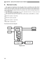
Страница 86: ...e systems are operated The symbol in drawings indicates transmission of mechanical drive and signals marked by together with the signal name indicates the flow of electrical signals 2 In descriptions of digital circuits on the stitcher 1 indicates a high signal voltage level while 0 indicates a low signal voltage level Voltage values differ according to circuit A microprocessor is used on the stit...

Страница 87: ...perations are controlled by the saddle stitcher controller PCB in response to commands from the host machine via the finisher unit Finisher unit control system Control system Guide plate drive system Paper positioning plate drive system Alignment drive system Stitcher drive system Delivery drive system Feed drive system Paper pushing plate drive system Paper folding roller drive system Figure 3 10...

Страница 88: ...various commands from the fin isher controller PCB The saddle stitcher controller PCB is also used to communicate the state of various sensors and switches to the finisher controller PCB in serial The functions of the major ICs mounted on the saddle stitcher controller PCB are as follows Q1 Controls the sequence of operations Q2 Contains the sequence program Q3 Controls the sequence of operations ...

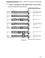
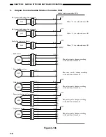
Страница 89: ...3 1 2 J11 7 9 8 3 J303 1 2 1 J203 3 2 3 J309 1 2 1 J209 3 2 PI2S J104 3 1 2 J11 10 12 11 PI1S J107 1 2 3 J11 15 Saddle stitcher controller PCB When the paper pushing plate motor is rotating alternately between 1 and 0 5V LUNGECLK When the front door is open 0 5V FDR When the paper folding motor is rotating alternately between 1 and 0 5V FLDCLK When the alignment plate is at home position 1 5V JOGH...

Страница 90: ...I14S J128 3 1 2 J9 10 5V When the paper pushing plate is at home position 1 LUNGEHP 12 11 PI15S J129 3 1 2 J9 13 5V When the paper pushing plate is at the leading edge 1 LUNGETOP 15 14 PI16S J131 3 1 2 J13 1 5V When the stitcher unit is housed 0 STPLHP 3 2 PI17S J132 3 1 2 1 3 2 4 2 3 J13 4 5V When paper is present in the vertical path 1 When the paper folding roller is at home position 0 VPJM 6 5...

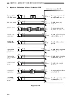
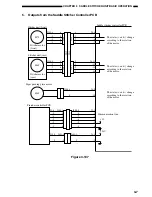
Страница 91: ...I20S MS6S MS7S 2 3 4 J123 5 2 J109 3 2 J110 3 3 J111 2 5V 1STPA STCHHP1 HKEMP1 2NDPA 3RDPA 1 4 3 2 J10 1 5 4 3 2 1 5 2 3 4 5 1 J304A J304 J204 7 J315 5 6 1 J8 3 2 1 3 2 7 5 6 No 1 paper sensor No 2 paper sensor No 3 paper sensor Stitcher home position sensor front Staple sensor front Stitcher home position sensor rear Staple sensor rear When the inlet door is closed 1 When the front door is closed...

Страница 92: ...B 3 B 4 A 5 J113 5 4 3 2 1 M5S The pulse signals change according to the rotation of the motor J5 1 A A 2 B 3 B 4 M1S 24V The pulse signals change according to the rotation of the motor J7 6 7 A B 8 B 9 A 10 J114 5 4 3 2 1 M4S 24V The pulse signals change according to the rotation of the motor J12 1 2 A B 3 B 4 A 5 J119 5 4 3 2 1 M3S The states and change according to the rotation of the motor J4 ...

Страница 93: ...S J315 4 J8 4 J2 1 2 3 4 5 Paper pushing plate motor M8S J108 1 2 J4 9 10 4 3 5 3 2 6 2 1 7 1 4 5 6 7 J400 1 J400 9 2 8 3 7 5 5 4 6 J401 1 2 J19 1 2 J401 1 2 J1 1 2 Communication line 5V 24V 6 6 J3 6 5 4 2 3 1 4 J305 J120 The states and change according to the rotation of the motor The states and change according to the rotation of the motor Stitcher unit rear Stitcher motor rear M6S J316 4 J8 11 ...

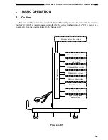
Страница 94: ...tack for delivery to the delivery tray according to the commands coming from the finisher controller PCB The machine s operation consists of the following 1 Receive sheets 2 Aligns the sheets 3 Stitches the stack 4 Feeds the stack 5 Folds and delivers the stack 1 Receive sheets 4 Feeds the stack 3 Stitches the stack 5 Folds and delivers the stack 2 Aligns the sheets Figure 3 201 ...

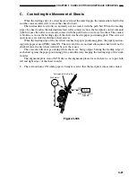
Страница 95: ...ation The vertical path while sheets are being output is configured by two paper deflecting plates The position of the sheets being output is set by the paper positioning plate so that the center of the stack matches the stapling folding position Sheets coming later are output closer to the delivery slot Paper positioning plate First sheet Second sheet Direction of delivery Figure 3 202 ...

Страница 96: ...heets in order each time a sheet of paper is output to the vertical path assembly The alignment plates are mounted at the edge of the vertical path assem bly The alignment plates also operate after stapling to prepare the stack for delivery Sheets Paper positioning plate Alignment plate Alignment plate Figure 3 203 ...

Страница 97: ... that they face the center of a stack The two stitchers are not operated simultaneously so as to prevent the paper from wrinkling between two staples and to limit the load on the power supply If only one sheet of paper arrives from the host machine stitching does not take place and the sequence goes to the next operation stack feeding Stitcher Staple Figure 3 204 ...

Страница 98: ...g position matches the height of the paper pushing plate and the paper folding roller nip The stack is moved forward by operating the paper positioning plate When the plate is oper ated the guide plate which has been covering the paper folding rollers also moves down so that the paper folding rollers directly face the stack Paper folding roller Guide plate Paper positioning plate Paper pushing gui...

Страница 99: ...er of the stack to move it in the direction of the paper folding rollers In response the paper folding rollers pick the stack along its center and fold it in two The paper folding rollers together with the delivery roller then move the stack along to output it on the delivery tray Delivery roller Paper folding roller Figure 3 206 ...

Страница 100: ... is handled by the feed rollers and the crescent roller and held in a predeter mined position The feed plate serve to move sheets by coming into contact with or moving away from sheets as needed The alignment plates put the stack into order each time a sheet is output The alignment plates are driven by the alignment motor M5S whose position is identified in reference to the number of motor pulses ...

Страница 101: ...3 15 CHAPTER 3 SADDLE STITCHER UNIT BASIC OPERATION Figure 3 301 ...

Страница 102: ...etection signal 3RDPA No 2 paper detection signal 2NDPA No 1 paper detection signal 1STPA PI21S Paper positioning plate home position detection signal PAPPOS Paper positioning plate paper detection signal PPOSPAR Tray paper detection signal TRYPAR Guide plate home position detection signal GIDHP Crescent roller position detection signal FDRLHP Delivery detection signal DELV Paper folding home posi...

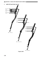
Страница 103: ...he following sheet from butting against the top of the existing stack Table 3 301 shows the relationship between sensors and paper sizes Sensor A3 LD B4 LG A4 R LT R No 1 paper sensor PI18S Used Used Used No 2 paper sensor PI19S Not used Used Used No 3 paper sensor PI20S Not used Not used Used Table 3 301 Each flapper is driven by its own solenoid Table 3 302 shows the relationship between solenoi...

Страница 104: ...3 18 CHAPTER 3 SADDLE STITCHER UNIT BASIC OPERATION 2 A3 LD Paper Path 3 sheets Figure 3 303 ...

Страница 105: ... sheets SL1S SL2S ON OFF No 1 paper sensor PI18S PI19S PI20S No 2 paper sensor No 3 paper sensor Passage of paper Passage of paper Non passage of paper Entry of First sheet PI18S PI19S PI20S Entry of Second sheet PI18S PI19S PI20S Entry of Third sheet Top edge Figure 3 304 ...

Страница 106: ...ath 3 sheets SL1S SL2S ON ON No 1 paper sensor PI18S PI19S PI20S No 2 paper sensor No 3 paper sensor Passage of paper Passage of paper Passage of paper Entry of First sheet PI18S PI19S PI20S Entry of Second sheet PI18S PI19S PI20S Entry of Third sheet Top edge Figure 3 305 ...

Страница 107: ...ies of operations is executed each time a sheet arrives When the leading edge of the first sheet reaches the paper positioning plate the paper position ing plate paper sensor PI8S turns ON The arrival of the second and subsequent sheets will not be checked since the first sheet will still be over the sensor The crescent roller keeps rotating while sheets are being output butting the leading edge o...

Страница 108: ... The solenoid turn OFF when the paper butts against the paper positioning plate The feed motor continues to rotate SL4S OFF M1S Figure 3 307 3 The solenoid turns ON when the next sheet arrives and the feed plate comes into contact SL4S ON M1S Figure 3 308 ...

Страница 109: ...wing briefly describes what takes place when the saddle stitching mechanism oper ates on two sheets 1 When the first sheet has been output the alignment plates butt against the left and right edges of the stack first alignment The alignment plates leave the home position in advance and remain in wait at points 10 mm from the edges of the stack Sheets Paper positioning plate Alignment plate Alignme...

Страница 110: ...gnment plates butt against the stack once again during which stitching takes place Figure 3 312 6 The alignment plates escape to points 10 mm from the edges of the stack after which folding and delivery take place Figure 3 313 7 When the first sheet of the following stack reaches the No 1 paper sensor the guide moves to a point 10 mm from the edge of the stack to be ready for the next alignment op...

Страница 111: ...try of 1st sheet Entry of 2nd sheet 1st sheet of follow ing stack entry In case of 2 sheets 1 Move to wait position 2 Stapling period 3 Paper folding delivery period 4 Move to following stack size wait position 1 2 3 4 Figure 3 315 M5S Alignment motor Alignment plate Alignment plate Alignment plate home position sensor PI5S Stack Paper positioning plate Figure 3 316 ...

Страница 112: ... of alignment The phase of the crescent roller is identified by the crescent roller phase sensor PI12S The flag for the crescent roller phase sensor is mounted to the crescent roller shaft The flag will leave the sensor while the roller shaft rotates turning the sensor ON or OFF enabling the assumption that the crescent roller is positioned at the opposite side of the stack Figure 3 319 The alignm...

Страница 113: ...h the stack alignment opera tion could be obstruct ed Sensor flag Crescent roller Figure 3 318 Alignment operation is started when the flag has covered the sensor and the crescent roller is away from the stack Figure 3 319 Crescent roller phase sensor PI12S First sheet Second sheet Feed motor stops Alignment operation Feed motor M1S Figure 3 320 ...

Страница 114: ...5S for detection of position and a staple sensor MS6S MS4S for detection of the presence absence of staples The stitcher base is designed so that it may be drawn out to the front from the saddle stitcher for replacement of the staple cartridge or removal of a staple jam The stitcher unit in sensor PI16S is used to make sure that the stitcher base is properly fitted to the saddle stitcher Safety sw...

Страница 115: ...nitiating the stitcher motor startup current helps decrease the load on the power supply The stitcher home position sensor MS7S MS5S is used to monitor the movement of the rotary cam enabling identification of individual stitcher operations The presence absence of staples inside the staple cartridge fitted to the stitcher is detected by the staple sensor MS6S MS4S The alignment plates keep both ed...

Страница 116: ...3 30 CHAPTER 3 SADDLE STITCHER UNIT BASIC OPERATION Cam Mount Figure 3 404 ...

Страница 117: ...n sensor PI21S for detecting the position of the paper folding rollers The paper pushing plate is driven by the paper pushing plate motor M8S and the drive of the paper pushing plate motor is monitored by the paper pushing plate motor clock sensor PI1S The paper pushing plate home position sensor PI14S and the paper pushing plate top position sensor PI15S are used to detect the position of the pap...

Страница 118: ... and where the paper pushing plate is located The position of the paper positioning plate is controlled in reference to the number of motor pulses coming from the paper positioning home position sensor PI7S At the same time as the paper positioning plate operates the guide plate lowers so that folding may take place PI13S Stitching ends Equivalent of specific number of pulses Paper positioning pla...

Страница 119: ...ing rollers excluding the center part is punched out This punched out area only feeds the paper as the paper feeding roller lower contacts the paper feeding roller upper only at the center of the roller to prevent the paper from wrinkling As the paper feeding roller lower contacts the paper feeding roller upper at their entire surfaces on the remaining half of the peripheral area paper folding sta...

Страница 120: ...er pushing plate home position sensor PI14S Paper pushing plate Paper pushing plate motor Paper folding motor M2S M8S Figure 3 503 Paper folding start position Paper folding feeding is performed Paper feeding is performed Paper folding home position sensor PI21S Sensor flag Delivery outlet Paper feed inlet Paper pushing plate Stack of sheets Figure 3 504 ...

Страница 121: ... sensor PI21S Sensor flag Delivery outlet Paper feed inlet Figure 3 505 Paper folding motor M2S Paper pushing plate motor M8S Paper pushing plate home position sensor PI14S Paper pushing plate top position sensor PI15S Delivery sensor PI11S Tray paper sensor PI6S Motor CW Motor CCW Paper folding home position sensor PI21S Equivalent of 10mm by paper folding motor Figure 3 506 ...

Страница 122: ...sure along the crease on the stack Then the paper folding rollers rotate normally and the paper pushing plate returns to its home position while the stack is being delivered This way a stack requiring a large force may properly be folded with less pressure 1 The paper pushing plate pushes the stack in the direction of the paper folding rollers M2S Paper folding motor M8S Paper pushing plate motor ...

Страница 123: ...e stack The paper pushing plate returns to its home position M2S Paper folding motor M8S Paper pushing plate motor Figure 3 510 Paper folding motor M2S Paper pushing plate motor M8S Delivery sensor PI11S Paper pushing plate top position sensor PI15S Paper pushing plate home position sensor PI14S Tray paper sensor PI6S Equivalent of 20 mm Equivalent of 20 mm reverse feeding Gripping of paper stack ...

Страница 124: ... the host machine may stop copying operation and indicate the presence of a jam on its control panel PI18S PI8S PI19S PI20S Figure 3 601 Table 3 601 No Sensor PI8S Paper positioning plate paper detection sensor PI11S Delivery sensor PI14S Paper pushing plate home position sensor PI15S Paper pushing plate top position sensor PI17S Vertical path paper sensor PI18S No 1 paper sensor PI19S No 2 paper ...

Страница 125: ...d mm sec Delivery speed mm sec Jam Load stops Figure 3 602 3 Inlet Stationary Jam The No 1 paper sensor PI18S No 2 paper sensor PI19S and No 3 paper sensor PI20S on the paper sensor PCB do not turn OFF when the stack has been fed for a specific period after the No 1 paper sensor PI18S turns ON The paper sensor used varies according to the paper size a A3 LD Stack PI18S PI18S No 1 paper sensor No 1...

Страница 126: ...shows two sensors checking for jams Single detection however uses only one sensor Figure 3 604 c A4 R LT R Stack PI18S PI19S PI20S PI18S PI19S Note The diagram shows three sensors checking for jams Single detection however uses only one sensor No 1 paper sensor No 1 paper sensor No 2 paper sensor No 3 paper sensor PI20S No 3 paper sensor No 2 paper sensor Feed motor Feed motor Jam Jam Jam T feedin...

Страница 127: ... Delivery Stationary Jam a By vertical path paper sensor The vertical path paper sensor PI17S does not turn OFF within a specific period of time feeding after the delivery sensor PI11S has turned ON i e the trailing edge of the stack does not leave the vertical path paper sensor PI17S Vertical path paper sensor PI17S Vertical path paper sensor Normal Jam Delivery sensor Delivery sensor Paper foldi...

Страница 128: ... finds that the respective cover is open during operation 8 Stitcher Staple Jam When the stitcher motor M7S M6S is rotating clockwise the stitcher home position sensor MS7S MS5S does not turn ON within 0 5 secs after it has turned OFF In addition the sensor turns ON within 0 5 secs after the motor has been rotated counterclockwise 9 Saddle Stitcher Feeding Delay Jam by the paper sensor for the pap...

Страница 129: ...d will not be supplied if any of the three door switches is open The 5V power is used to drive sensors and ICs J19 1 J3 2 J1 1 J2 5 Finisher controller PCB Circuit breaker Saddle stitcher controller PCB Inlet door switch Front door switch Delivery door switch Motor systems Solenoids Sensors Logic Figure 3 701 2 Protective Mechanisms The 24 VDC power supply used for motors and solenoids is equipped...

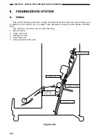
Страница 130: ...when disassembling and assembling the machine 1 Before performing disassembly and assembly be sure to unplug the power plug for safety s sake 2 Assemble parts by following the disassembly procedure in reverse unless otherwise mentioned 3 Assemble screws etc making sure that their type length and diameter and location of use are correct 4 In principle do not operate the machine with any parts remov...

Страница 131: ...nt lower door 5 Tray 1 6 Tray 2 7 Grate shaped upper guide 6 8 Grate shaped lower guide 6 9 Saddle Stitcher delivery tray 10 Sub support upper cover 2 11 Sub support lower cover 2 12 Rear cover 3 13 Rear lower cover 4 Figures in parenthese indicate the number of mounting screws A Externals and Controls Figure 4 102 12 13 10 11 ...

Страница 132: ...and remove the bush ing 3 center 3 Remove the screw 4 and remove the bush ing top 5 Then remove the front door assembly 4 5 1 3 2 Figure 4 103 2 Removing the Rear Cover 1 Open the upper door assembly 1 2 Remove the three screws 2 and lift the rear cover 3 to remove 1 Upper door assembly 2 Screws 3 Rear cover Figure 4 104 3 2 1 ...

Страница 133: ...per Door Assembly 1 Open the upper door assembly 1 2 Remove the two claws 2 and remove the upper door assembly Figure 4 105 4 Removing the Front Cover 1 Open the front door assembly 1 2 Remove the screw 2 and remove the front cover 3 Figure 4 106 1 2 1 3 2 ...

Страница 134: ...ole 2 while supporting the tray as sembly 1 2 Release the tray lift motor one way gear and lower the tray 1 2 unit Figure 4 107 1 2 1 2 3 4 3 Remove the harness band 1 of the tray 1 and 2 from the bracket 2 Cut the har ness band 1 to separate the harnesses of the tray 1 and 2 Caution Replace the cut harness band with the new one when assembling 4 Disconnect 2 connectors 3 and remove 1 screw 4 5 Di...

Страница 135: ...to remove Figure 4 110 1 2 3 4 8 Removing the Tray 1 and 2 Lift Motor 1 Remove the tray 1 2 2 Remove two screws 1 and two lift blocks 2 3 Remove the five screws 3 and remove the tray from the tray unit Figure 4 111 3 3 1 2 2 4 Remove the cable from 4 cable hooks of the tray lower cover 1 and then remove 5 screws 3 5 Release 2 hooks 4 to remove the tray frame 5 from 2 hooks 6 the tray lower cover F...

Страница 136: ...moving the Grate Shaped Upper Guide 1 Remove the slide guide 1 and end caps 2 2 Release the tray lift motor gear clutch 6 with a screwdriver or similar object while supporting the tray assembly and gently lower the tray assembly down to its lowest position 3 Remove the five screws 3 M4 4 Remove the screw 4 M3 and remove the grate shaped upper guide 5 1 5 3 4 6 2 2 3 ...

Страница 137: ...nt Figure 4 115 4 Free the harness 9 from the harness stop 8 5 Disconnect the two connectors 10 and re move the grate shaped lower guide 7 Figure 4 116 3 4 6 5 2 1 8 10 9 7 Caution To remove a sub support remove the front sub support 2 The rear sub support 6 is adjustable If the rear sub support 6 has been removed be sure to adjust the rear sub support screw to the marking at which it was set prio...

Страница 138: ...ight guide assembly 3 Figure 4 118 3 2 1 4 5 11 Installing the Rear Sub Support 1 Install the front sub support 1 Loosely fasten the rear sub support 2 2 Install tray 2 Fasten the rear sub support so that the tray drive gear 3 is placed at the center of the rack gear 4 of the rear sub support when tray 2 is at the upper limit position and the lower limit position 3 Move tray 2 by hand and check th...

Страница 139: ... lower guide see I A 7 4 Remove the harness from the two harness stops 1 and disconnect the four connec tors 2 5 Remove the screw 3 and remove the sta pler stay holder 4 Figure 4 119 6 Remove the three screws 5 and slide out the swing unit 6 towards you Figure 4 120 7 Remove the claws of the two knurled belt holders front 7a rear 7b and remove the swing unit Figure 4 121a 3 4 2 1 6 5 5 5 7a ...

Страница 140: ...1 Remove the finisher controller PCB see I C 1 2 Remove the ground lead 1 and the three screws 2 and pull down PCB base 3 to wards you Figure 4 122 3 Remove the harness leads 5 from the two edge saddles 4 and remove the PCB base Figure 4 123 1 2 3 2 5 4 4 Figure 4 121b 7b ...

Страница 141: ...er assembly side Figure 4 126 Caution Before re attaching the removed feed drive unit back on the finisher unit loosen the move gear stop screw 8 to relieve the tension and then fasten the screw after attaching the feed drive unit The move gear attachment must be adjusted also when removing and attaching the swing unit If you forget to fasten the screw the gear teeth may disengage resulting in def...

Страница 142: ...e the stapler assembly to the front 2 Remove the screw 1 and slide out the sta pler assembly 2 3 Disconnect the connector 4 of the stapler assembly 3 2 1 4 3 4 Remove the front cover see I A 4 5 Remove the screw 4 and remove the guide support plate assembly 5 Then remove the buffer roller assembly 6 Figure 4 127 6 5 4 ...

Страница 143: ...Finisher Controller PCB 1 Remove the rear cover 2 Disconnect the 17 connectors 1 3 Remove the four screws 2 and remove the finisher controller PCB 3 Figure 4 131 2 1 3 2 2 4 Remove the two screws 6 from the sta pler cover 5 and remove the stapler Figure 4 130 5 6 ...

Страница 144: ...ing the Front Lower Door Assembly 1 Open the front lower door assembly 1 2 Remove the screw 2 and remove the bush ing 3 and then remove the front lower door assembly Figure 4 201 2 Removing the Rear Lower Cover 1 Remove the four screws 1 and remove the rear lower cover 2 Figure 4 202 1 3 2 1 2 1 ...

Страница 145: ... the front inside cover 5 Figure 4 203 4 Removing the Saddle Stitcher Delivery Tray Assembly 1 Lift up the open close lever 2 of the saddle stitcher delivery tray assembly 1 and open the saddle stitcher delivery tray assembly Figure 4 204 2 Remove the door shaft 3 in the direction of the arrow and slide out towards the front of the saddle stitcher delivery tray assem bly 4 Figure 4 205 1 4 4 3 5 4...

Страница 146: ...addle stitcher delivery tray as sembly 8 Figure 4 206 Figure 4 207 5 Removing Upper Delivery Guide Assembly 1 Remove the grate shaped lower guide see I A 10 2 Remove the two screws 1 and ground lead 2 and remove the upper delivery guide assembly 3 6 Removing the PCB Cover 1 Remove the four screws 1 and remove the PCB cover 2 Figure 4 208 7 5 6 8 1 3 2 1 1 2 1 ...

Страница 147: ...he front lower door assembly see II A 1 4 Remove the rear lower cover see II A 2 5 Remove the front inside cover see II A 3 6 Remove the saddle stitcher delivery tray as sembly see II A 4 Figure 4 209 Figure 4 210 7 Remove harness stop 3 and harness lead 4 8 Remove the upper delivery guide see II A 5 9 Remove the PCB cover see II A 6 10 Disconnect two connectors 1 and remove the two screws 2 1 2 3...

Страница 148: ...ws 6 and remove the saddle stitcher unit 7 by moving it in the pick up direction Figure 4 211 Figure 4 212 Figure 4 213 Caution When removing the saddle stitcher unit from the finisher unit body prevent the timing belt 8 from catching on the communications cable bracket 9 5 6 6 7 9 8 ...

Страница 149: ...sembly see II A 1 2 Remove the front inside cover see II A 3 3 Remove the upper delivery guide see II A 5 4 Remove the PCB cover see II A 6 5 Disconnect the two connectors 1 6 Disconnect two connectors 2 remove the three screws 3 and remove the paper pushing motor mount 4 Figure 4 214 Figure 4 215 1 2 2 3 4 ...

Страница 150: ...4 20 CHAPTER 4 MECHANICAL CONSTRUCTION 7 Remove the tension springs front 5 rear 6 Figure 4 216 Figure 4 217 5 6 ...

Страница 151: ...MECHANICAL CONSTRUCTION 8 Remove the two C rings 7 and remove the sensor flag 8 and two bearings 9 at the rear Figure 4 218 9 Remove the two C rings 10 and remove the two gears 11 at the front Figure 4 219 9 7 8 11 10 ...

Страница 152: ... the two alignment plates 15 13 Slide the paper folding roller 16 to the front and pull it out in the delivery direc tion Figure 4 220 Figure 4 221 3 Installing the Paper Folding Roller 1 Attach the gear 2 so that the grooved sec tion 1 on the gear is facing the grooved section 1 on the paper folding roller to align the phases Figure 4 222 12 13 15 14 14 16 2 1 ...

Страница 153: ...ll out the stitcher mount unit 4 to the front Figure 4 224 5 Adjusting the Stitcher Position 1 Remove the front lower door see II A 1 2 Remove the front inside cover see II A 3 3 Open the front door assembly 4 Pull out the stitcher mount unit to the front then pull out the stitcher towards you and then pull the stitcher down 5 Remove the three screws 1 and remove the stitcher mount unit cover 2 1 ...

Страница 154: ...e the center guide plate 5 and front guide plate 4 one screw each If you must ad just the rear stitcher remove the center guide plate 5 and the rear guide plate 6 one screw each Figure 4 227 8 If you must adjust the front stitcher loosen the two screws 8 on the stitcher mount 7 If you must adjust the rear stitcher loosen the two screws 9 Figure 4 228 3 6 5 4 9 8 7 ...

Страница 155: ...ighten the screws 12 on the mount to fix the two in place Figure 4 230 6 Removing the Positioning Plate Unit 1 Remove the saddle stitcher controller PCB see II C 1 2 Disconnect the two connectors 1 remove the three harness stops 2 and remove the harness leads 3 from the two edge saddles 4 3 Remove the two screws 5 slide the posi tioning plate unit 6 once towards the front and remove from the rear ...

Страница 156: ...I A 2 3 Remove the claw 1 of the No 1 deflecting plate bushing and pull out the No 1 deflect ing plate shaft 2 toward the rear The pro cedure is the same for the No 2 paper de flecting plate Figure 4 233 Figure 4 232 4 After detaching the front shaft of the No 1 paper deflecting plate 3 from the front side plate remove the No 1 paper deflecting plate 1 2 3 1 2 ...

Страница 157: ...CONSTRUCTION C PCBs 1 Removing the Saddle Stitcher Controller PCB 1 Remove the PCB cover see II A 6 2 Remove the four screws 1 and 14 connec tors 2 and remove the saddle stitcher con troller PCB 3 Figure 4 234 1 1 1 1 2 3 2 2 2 ...

Страница 158: ...delivery tray is signifi cantly deteriorated causing paper to drop etc 2 screws are needed to install the support tray Refer to the pats list for the parts numbers and so on 1 Take off the suddle delivery tray see II A 4 2 Install the support tray 2 to the saddle stitcher delivery tray 1 with 2 screws 3 Install the saddle stitcher delivery tray Figure 4 235 Figure 4 236 2 3 1 ...

Страница 159: ...LLY REPLACED PARTS 5 1 A Finisher Unit 5 1 B Saddle Stitcher Unit 5 1 II CONSUMABLES AND DURABLES 5 2 A Finisher Unit 5 2 B Saddle Stitcher Unit 5 2 III PERIODICAL SERVICING 5 2 IV FIRMWARE UPDATING 5 3 A Finisher Unit 5 3 B Saddle Stitcher Unit 5 5 ...

Страница 160: ...N I PERIODICALLY REPLACED PARTS A Finisher Unit The finisher unit does not have parts that must be replaced on a periodical basis B Saddle Stitcher Unit The saddle stitcher unit does not have parts that must be replaced on a periodical basis ...

Страница 161: ... Unit No Name Q ty Estimated Life Remarks 1 Stapler 1 500 000 operations 5 000 operations cartridge 2 Feed belt 2 1 000 000 copies 3 Paddle 2 1 000 000 copies Paddle unit 4 Paddle rubber only B Saddle Stitcher Unit No Name Q ty Estimated Life Remarks 1 Stitcher 2 200 000 operations 2 000 operations cartridge III PERIODICAL SERVICING Item Interval Work Remarks Feed belt Host machine minimum servici...

Страница 162: ...e correct Download jig K PWA DLM 320 2 Turn OFF the power of the equipment 3 Connect the finisher to the equipment after the finisher rear cover is removed See chapter 4 I A 2 for removing the rear cover 4 Connect the download jig to the jig connecter on the finisher controller PCB Connector Identification for the ROM installation direction LED ROM Download jig ...

Страница 163: ...umed that the update fails if the LED does not start blinking even though 1 min has passed or it blinks fast In this case turn OFF the power and check the following items Then clear the problem and restart updating from the beginning Is the download jig connected properly Is the ROM installed to the download jig properly Is the updating data written on the ROM of the download jig correctly Are the...

Страница 164: ...load jig K PWA DLM 320 2 Turn OFF the power of the equipment 3 Remove the PCB cover on the saddle stitcher See chapter 4 II A 6 for removing the PCB cover 4 Connect the download jig to the jig connecter on the saddle stitcher controller PCB to connect the finisher with the equipment Connector Identification for the ROM installation direction LED ROM Download jig ...

Страница 165: ...that the update fails if the LED does not start blinking even though 1 min has passed or it blinks fast In this case turn OFF the power and check the following items Then clear the problem and restart updating from the beginning Is the download jig connected properly Is the ROM installed to the download jig properly Is the updating data written on the ROM of the download jig correctly Are the down...

Страница 166: ...er unit 6 1 B Electrical System saddle stitcher unit 6 5 II ARRANGEMENT OF ELECTRICAL PARTS 6 7 A Finisher Unit 6 7 B Saddle Stitcher Unit 6 14 C Light Emitting Diodes LED and Check Pins by PCB 6 20 III TROUBLESHOOTING 6 22 A Finisher Unit 6 22 B Saddle Stitcher Unit 6 32 ...

Страница 167: ...the mecha nism stops while the tray in question is being adjusted at the same time LED1 turns OFF 6 Shift all bits on SW3 to OFF and turn OFF the host machine once 2 Adjusting the Alignment Position If you have replaced the finisher control ler PCB or if an alignment fault occurs adjust as follows Performing the steps will affect all paper sizes 1 Turn the host machine OFF 2 Remove the rear cover ...

Страница 168: ...r unit 3 Set SW3 on the finisher controller PCB as indicated ON 1 2 3 4 5 6 7 8 Figure 6 104 4 Turn the host machine ON while 0 but ton and 8 button are pressed simultane ously 5 If you are using A4 paper press SW1 on the finisher controller PCB If you are us ing LT paper press SW2 on the finisher controller PCB Pressing SW1 2 will open the swing guide and cause the feed belt to rotate 6 Within 5 ...

Страница 169: ...ove the stack of sheets from the fin isher delivery taking care to prevent the offset of the output sheets from changing 7 If the stapling position is correct set all bits on SW3 to OFF to end the adjust ments If you need to change the stapling position on the other hand go to the next step 8 To suit the position of the staple on the paper press SW1 or SW2 on the finisher controller PCB as many ti...

Страница 170: ...her controller PCB The current setting values are displayed at LED1 Adjustment value 0 Lights for 1 second once Adjustment value N Blinks lights for 0 2 second for N times Adjustment value N Lights for 1 second once and blinks lights for 0 2 second for N times The adjustment width is 0 72mm for each N 1 Table 6 101 12 Turn the host machine OFF and then set SW3 on the finisher controller PCB as ind...

Страница 171: ...6 7 8 Do not change bits 5 through 8 Figure 6 113 3 Turn the host machine ON while 0 but ton and 8 button are pressed simultane ously 4 Remove the rear cover of the saddle stitcher unit and tape the actuator of the inlet cover sensor PI9S and the inlet door switch MS1S of the saddle stitcher unit in place 5 Before inserting the paper mark the top of the paper you will be using two sheets of A3 or ...

Страница 172: ...units of 0 5 mm OFF ON ON 3 OFF ON OFF 2 OFF OFF ON 1 OFF OFF OFF 0 ON OFF ON 1 ON ON OFF 2 ON ON ON 3 Do not touch the following bit 6 bit 7 bit 8 ON OFF OFF Table 6 102 12 Set bits 1 through 4 on DIPSW1 to OFF 2 Stitching Position adjusting cen ter stitching Use the host machine adjustment mode to perform the following 10 Measure the distance L between the stitching position and the folding posi...

Страница 173: ...6 CHAPTER 6 TROUBLESHOOTING II ARRANGEMENT OF ELECTRICAL PARTS A Finisher Unit ...

Страница 174: ...6 CHAPTER 6 TROUBLESHOOTING 1 Sensors PI11 PS1 PI17 PI1 PI18 PI10 PI20 PI14 PI6 PI4 PI3 PI16 PI12 PI5 PI7 PI15 PI8 PI21 PI22 PI25 Figure 6 201 ...

Страница 175: ...on PI10 Detects delivery motor clock pulses PI11 Detects paper on tray 1 PI12 Detects paper on tray 2 PI14 Detects paper in the buffer path PI15 Detects the finisher joint PI16 Detects the state open of the door PI17 Detects paper at the inlet to the buffer path PI18 Detects the state open of the swing guide PI20 Detects swing guide clock PI21 Detects edging of staples inside stapler PI22 Detects ...

Страница 176: ... of the front door and the upper door MS2 Detects the state closed of the swing guide 1 MS3 Detects the safety range MS4 Detects the state closed of the shutter MS6 Detects the state closed of the swing guide 2 MS7 Detects the cartridge inside stapler MS8 Detects the presence absence of staples inside stapler MS9 Detects the tray coming close Table 6 202 ...

Страница 177: ...4 M6 M5 M10 Figure 6 203 Name Notation Function Motor M1 First Feed motor M2 Delivery motor M3 Alignment motor M4 Stapler shift motor M5 Tray 1 lift motor M6 Staple motor M7 Swing motor M8 Second feed motor M9 Inlet feed motor M10 Tray 2 lift motor Table 6 203 ...

Страница 178: ... 4 Solenoids SL2 SL3 SL1 SL6 SL5 SL7 Figure 6 204 Name Notation Function Solenoid SL1 Flapper solenoid SL2 Buffer inlet solenoid SL3 Buffer outlet solenoid SL5 Paddle solenoid SL6 Escape solenoid SL7 Belt escape solenoid Table 6 204 ...

Страница 179: ...6 13 CHAPTER 6 TROUBLESHOOTING 5 PCBs 1 3 2 4 Figure 6 205 Reference Name 1 Finisher controller PCB 2 Relay PCB 4 3 Relay PCB 3 Table 6 205 ...

Страница 180: ...6 14 CHAPTER 6 TROUBLESHOOTING B Saddle Stitcher Unit 1 Photointerrupters PI11S PI9S PI8S PI7S PI6S PI13S PI4S PI3S PI2S PI18S PI19S PI20S PI1S PI12S PI5S PI14S PI15S PI16S PI17S PI21S Figure 6 206 ...

Страница 181: ... PI8S Detects paper on the paper positioning plate PI9S Detects the state open of the inlet cover PI11S Detects paper in the delivery area PI12S Detects the phase of the crescent roller PI13S Detects the guide at home position PI14S Detects the paper pushing plate at home position PI15S Detects the paper pushing plate at top position PI16S Detects the state in of the stitcher unit PI17S Detects pa...

Страница 182: ...es MS1S Detects the state open of the inlet door MS2S Detects the state open of the front door MS3S Detects the state open of the delivery door MS4S Detects the presence of staples rear MS5S Detects stitching home position rear MS6S Detects the presence of staples front MS7S Detects stitching home position front Table 6 207 ...

Страница 183: ...M4S M5S M3S M6S Figure 6 208 Name Notation Function Motor M1S Feed motor M2S Paper folding motor M3S Guide motor M4S Paper positioning plate motor M5S Alignment motor M6S Stitcher motor rear M7S Stitcher motor front M8S Paper pushing plate motor Table 6 208 ...

Страница 184: ...TROUBLESHOOTING 4 Solenoids SL1S SL2S SL4S Figure 6 209 Name Notation Function Solenoid SL1S No 1 paper deflecting plate solenoid SL2S No 2 paper deflecting plate solenoid SL4S Feed plate contact solenoid Table 6 209 ...

Страница 185: ...6 19 CHAPTER 6 TROUBLESHOOTING 5 PCBs 1 2 Figure 6 210 Reference Name 1 Saddle stitcher controller PCB 2 Paper sensor PCB Table 6 210 ...

Страница 186: ...y Do not touch them in the field 1 Finisher Controller PCB SW1 SW2 SW3 LED2 LED1 J14 1 6 J3 J2 J6 J11 J16 J24 J17 J10 J7 J1 J19 J5 J27 J26 J25 J31 J8 J23 J21 J12 J9 B A 1 8 1 7 11 1 1 1 7 1 9 1 1 6 1 3 1 1 2 1 2 13 1 12 1 1 4 14 1 1 14 A 10 1 A B 1 1 17 19 33 10 B 15 1 1 9 2 11 10 1 11 Figure 6 215 Switch Function SW1 Adjust the height sensor alignment plate position stapling position and move the...

Страница 187: ...SW2 LED1 LED2 LED3 J31 1 9 1 8 1 15 J19 2 1 J1 J7 J4 Figure 6 216 Switch Function DIPSW1 bits 1 2 Starts correction of discrepancy between stitching position and folding position DIPSW1 bits 6 8 Stores corrected settings for stapling position and folding position SW2 Starts correction of discrepancy between stitching position and folding position Table 6 216 ...

Страница 188: ...DC controller PCB Wiring Finisher controller PCB Host machine DC controller PCB Step 1 2 3 Yes No Yes No Yes No Action End Correct it End Mulfunction of the host machine Checks Turn the host machine OFF then ON Is the problem corrected Is the wiring between the finisher controller PCB and the saddle stitcher controller PCB normal Measure the voltage between J19 1 and J19 2 on the finisher controll...

Страница 189: ... Wiring Step 1 2 3 Yes No Yes No Yes No Action Connect the connector Replace the finisher controller PCB Replace the height sensor Correct the wiring Checks Turn the host machine OFF then ON Is the problem corrected Is the wiring between the finisher controller PCB and the sensors normal Measure the voltage between J6 2 and J6 4 on the finisher controller PCB Is it 5 VDC Cause Finisher controller ...

Страница 190: ...very roller by hand Does it turn smoothly Check the delivery motor clock sensor Is the sensor normal Does the voltage between J11 4 and J11 5 on the finisher controller PCB change to 24 VDC as soon as the delivery motor starts to rotate Cause Deliver roller Delivery motor clock sensor PI10 Finisher controller PCB Step 1 2 3 Yes No No No No Yes Action Correct mechanical operation Replace the sensor...

Страница 191: ... Checks Check the alignment plate home position sensor Is it normal Is the wiring between the finisher controller PCB and the alignment plate motor normal Is there any mechanical obstacle in the path of the alignment plate Replace the alignment motor Is the problem corrected Cause Alignment plate home position sensor PI6 Wiring Alignment plate Alignment motor M3 Finisher controller PCB Step 1 2 3 ...

Страница 192: ...e Stapler shift motor M4 Finisher controller PCB Step 1 2 3 4 Yes No No No Yes Yes No Action Replace the sensor Correct the wiring Remove the mechanical obstacles End Replace the finisher controller PCB Checks Turn the swing motor in reverse by hand Does the swing guide move up and down Is the swing guide closed detection switch 2 normal Does the swing motor rotate in reverse at a specific timing ...

Страница 193: ...on Correct the swinging mechanism Replace the sensor Replace the motor Replace the finisher controller PCB Checks Check the safety range switch Is the switch normal Is the safety range detection switch pressed correctly Check the swing guide closed detection switch 2 Is the switch normal Is the swing guide closed detection switch 2 pressed correctly Cause Safety range switch MS3 Swing guide closed...

Страница 194: ...om the finisher controller PCB to the tray 1 lift motor Is the wiring normal Cause Tray 1 home position sensor PI8 Tray 1 lift mechanism Finisher controller PCB Wiring Tray 1 lift motor M5 Step 1 2 3 4 Yes No No No No No Yes Action Replace the sensor Correct the mechanism Replace the finisher controller PCB Correct the wiring Replace the tray 1 lift motor Checks Check the tray 2 lift mechanism Is ...

Страница 195: ...e tray 1 lift motor Checks Does the tray 2 move up down Is the motor supplied withpower by the finisher controller PCB as soon as the tray 2 moves up down Is there a fault in the tray 2 lift mechanism Check the wiring from the finisher controller PCB to the tray 2 lift motor Is the wiring normal Cause ___ Finisher controller PCB Tray 2 lift mechanism Wiring Tray 2 lift motor M10 Step 1 2 3 4 Yes N...

Страница 196: ...em correctly Correct mechanism from the shutter upper lower bar to the gear of the feed roller 2 Replace the sensor Replace the finisher controller PCB Checks Does the second feed motor rotate in reverse at a specific timing Are the shutter and the shutter upper lower bar engaged correctly Turn the feed roller 2 in reverse by hand Does the shutter upper lower bar move up down Is the shutter closed...

Страница 197: ...ctly Check the shutter closed detection switch Is the switch normal Is the shutter closed detection switch pressed correctly Cause Safety range switch MS3 Shutter closed detection switch MS4 Finisher controller PCB Step 1 2 3 4 Yes No No No No No Yes Action Replace the switch Correct mechanical operation Replace the switch Correct the mechanism Replace the finisher controller PCB ...

Страница 198: ...rive mechanism If a fault is found correct it Otherwise go to step 3 End Replace the saddle stitcher controller PCB Checks Check the paper folding motor clock sensor Is the sensor normal Check the paper folding home position sensor Is the sensor normal Does the paper folding motor operate at a specific timing Replace the paper folding motor Is the problem corrected Cause Paper folding motor clock ...

Страница 199: ...late drive mechanism If a fault is found correct it Otherwise go to step 3 End Replace the saddle stitcher controller PCB Checks Check the alignment plate home position sensor Is the sensor normal Does the alignment motor operate at a specific timing Replace the alignment motor Is the problem corrected Cause Alignment plate home position sensor PI5S Saddle stitcher controller PCB Alignment motor M...

Страница 200: ... If normal replace the controller PCB Replace the front or the rear stitcher Checks Check the paper pushing plate home position sensor Is the sensor normal Check the paper pushing plate top position sensor Is the sensor normal Does the paper pushing plate motor operate at a specific timing Replace the paper pushing plate motor Is the problem corrected Cause Paper pushing plate home position sensor...

Страница 201: ...cher controller PCB Check the paper pushing plate drive mechanism If a fault is found correct it Otherwise go to step 3 End Replace the saddle stitcher controller PCB Checks Check the paper pushing plate motor clock sensor Is the sensor normal Does the paper pushing plate motor operate at a specific timing Replace the paper pushing plate motor Is the problem corrected Cause Paper pushing plate mot...

Страница 202: ...iring Power supply Ground Step 1 2 3 4 Yes No No Yes No No Action Connect the connectors Correct the wiring Replace the saddle stitcher controller PCB Checks Are the connectors of the paper pushing plate home position sensor and the saddle stitcher controller PCB connected correctly Is the wiring between the sensor and the saddle stitcher broken Is 5 VDC present at J9 10 on the saddle stitcher con...

Страница 203: ...ce the saddle stitcher controller PCB Checks Check the switch actuator of the inlet door Do the switch and the sensor operate correctly Check the inlet door switch Is the switch normal Measure the voltage at J10 8 on the saddle stitcher controller PCB with the inlet cover open Is it 5 V Measure the voltage between J19 1 and J19 2 on the finisher controller PCB Is it 24 V Cause Switch actuator Inle...

Страница 204: ...ep 1 2 3 Yes No No No Yes No Action Correct the mechanism Replace the switch The sensor is faulty Replace the sensor Replace the saddle stitcher controller PCB Checks Check the delivery door switch actuator Do the switch and the sensor operate correctly Check the delivery door switch Is the switch normal Measure the voltage at J11 9 on the saddle stitcher controller PCB with the delivery door open...

Страница 205: ...NDIX A FINISHER UNIT GENERAL TIMING CHART A 1 B SADDLE STITCHER UNIT GENERAL TIMING CHART A 2 C SIGNAL AND ABBREVIATIONS A 3 D FINISHER UNIT CIRCUIT DIAGRAM A 14 E SADDLE STITCHER UNIT CIRCUIT DIAGRAM A 18 ...

Страница 206: ...M8 Delivery motor M2 Staple tray sensor PI4 Alignment motor M3 Alignment position home position sensor PI6 Swing motor M7 Swing guide open sensor PI18 Swing guide closed detecting switch MS2 Paddle solenoid SL5 Belt escape solenoid SL7 Staple motor M6 Staple home position sensor PI22 Stapler shift motor M4 Height sensor PS1 Tray 1 lift motor M5 Operation start signal Host machine delivery signal M...

Страница 207: ... Stitcher motor front M7S Stitcher home position sensor front MS7S Stitcher motor rear M6S Stitcher home position sensor rear MS5S Guide home position sensor PI13S Guide motor M3S Paper positioning plate paper sensor PI8S Paper positioning plate home position sensor PI7S Paper positioning plate motor M4S Paper pushing plate home position sensor PI14S Paper pushing plate top position sensor PI15S P...

Страница 208: ...o 1 PAPER SENSOR DETECT Signal 2NDPA No 2 PAPER SENSOR DETECT Signal 3RDDPA No 3 PAPER SENSOR DETECT Signal DELV DELIVERY DETECT Signal DELVMS DELIVERY DOOR OPEN DETECT SWITCH Signal EJCVR DELIVERY DOOR OPEN DETECT Signal FDR FRONT DOOR OPEN DETECT Signal FDRLHP CRESCENT ROLLER PHASE DETECT Signal The following presents the abbreviations of signals used in this manual and in drawings and the mean ...

Страница 209: ...04L 03CZ 6Y J204LH BU03P TZ S LF J123DH 175694 3 1 2 3 J204D 03CZ 6Y 1 2 3 J125 03XR 6Y P 1 2 3 4 5 J124 05XR 6Y P MT5 2 1 M7 Swing motor 2 1 M2 Delivery motor 1 2 3 J134 03XR 6Y P J208LH BU07P TZ S LF 1 2 3 4 5 6 7 J208L 07CZ 6Y 10 9 8 2 3 4 5 6 1 7 J11 10CZ 6Y 5 4 3 2 1 M3 Alignment motor 1 2 SL5 Paddle solenoid 1 2 J128D 02XR 6Y P J128DH 8 292155 2 1 2 J128L MAKER 1 2 SL6 Escape solenoid 1 2 3 ...

Страница 210: ...3 J110 03XR 6Y P 3 2 1 PI14 Buffor path paper sensor 1 2 3 4 5 6 7 8 9 J24 09CZ 6Y 1 2 J500D 02XR 6Y P 1 2 3 4 J213L 04CZ 6Y J213DH BU04P TZ S LF 2 3 1 J206L 316087 1 1 2 J701D 02XR 6Y P 9 8 2 3 4 5 6 1 7 J202D 09XR 6Y P 1 2 SL3 Buffer outlet solenoid 1 2 J109L 173977 2 1 2 J107L 173977 2 1 2 J109D 02XR 6Y P J109DH 175694 2 1 2 3 4 J212D 04CZ 6Y 1 2 3 4 J212L 04CZ 6Y 6 5 4 3 2 1 M9 Inlet feed moto...

Страница 211: ... H J223LH BU13P TR P H 13 12 11 8 1 2 3 4 5 6 7 9 10 J223L PHNR 13 H 12 11 8 1 2 3 4 5 6 7 9 10 J222D PHNR 12 H J222LH BU12P TR P H 12 11 8 1 2 3 4 5 6 7 9 10 J222L PHNR 12 H 2 1 J221D 51067 0200 2 1 J221L 51114 0200 13 12 11 8 1 2 3 4 5 6 7 9 10 J26 PHNR 13 H 2 3 1 J138 1 172075 1 12 11 8 1 2 3 4 5 6 7 9 10 J25 PHNR 12 H 2 1 J27 VHR 2N MT6 1 2 3 4 5 6 J14 06CZ 6Y 1 2 3 J201 8 292112 3 1 2 3 J8010...

Страница 212: ... ADDRESS18 1 3 5 7 2 4 6 8 RA15 100 0 063W 1 3 5 7 2 4 6 8 RA14 100 0 063W 1 3 5 7 2 4 6 8 RA12 100 0 063W 1 3 5 7 2 4 6 8 RA13 100 0 063W 1 3 5 7 2 4 6 8 RA11 100 0 063W MD0_CON 5V CS_CON CS_CON FLASH_AD SWINGM_CK0 2 1 R428 100 0 1W RESET0 8 7 22K 0 063W RA5 6 5 22K 0 063W RA5 4 3 22K 0 063W RA5 2 1 22K 0 063W RA5 2 1 R427 100 0 1W 2 1 R426 100 0 1W 2 1 R425 100 0 1W LWR 2 1 R34 100 0 1W 8 6 4 2 ...

Страница 213: ... 12 11 2 1 IC6 IC62C256 45U 2 1 C12 1U 16V 5V 5V 2 1 C7 1U 16V 2 1 SKHVBB SW2 1 2 SKHVBB SW1 1 10 11 12 13 14 15 16 2 3 4 5 6 7 8 9 DIPSW1 SSGM18 TRAYS1 TRAYS0 STPL_CON0 CARTRIDGE0 STPL_READY0 HOOK0 1 50 2 49 3 48 4 47 5 46 6 45 7 44 8 43 9 42 10 41 11 40 12 39 13 38 14 37 15 36 16 35 17 34 18 33 51 32 52 31 53 30 54 29 55 28 56 27 57 26 58 25 59 24 60 23 61 22 62 21 63 20 64 19 IC4 M38881M2 010GP...

Страница 214: ...A9 DATA10 DATA11 DATA12 DATA13 DATA15 FEED2M_I1 FEED2M_I0 FEEDM_I1 LAMP1 HWR RD 5 J31 1 2 10K 0 1W R406 FLASH_READY 1 2 10K 0 1W R212 32 J31 5V 33 J31 5V 17 J31 16 J31 15 J31 31 J31 14 J31 30 J31 13 J31 29 J31 12 J31 28 J31 27 J31 10 J31 9 J31 25 J31 8 J31 24 J31 7 J31 23 J31 11 J31 26 J31 6 J31 21 J31 4 J31 20 J31 3 J31 19 J31 2 J31 18 J31 1 J31 PUNCH_UPCOVER PUNCH_FCOVER REG_HP PUNCH_HP PUNCH_UM...

Страница 215: ... 50V 2 1 R50 10K 0 1W 5V 5U 7 J2 6 J2 5V 2 1 4 7K 0 1W R42 5V 1 2 R44 4 7K 0 1W 5V 2 1 R46 4 7K 0 1W 5V 1 2 4 7K 0 1W R47 OPEN4 1 2 ICP13 20N3000 U 1 2 ICP12 20N3000 U OPEN1 OPEN2 OPEN3 1 2 ZD5 HZS18 2 E 2 1 ZD3 HZS18 2 E 2 J7 3 J7 1 2 100P 50V C33 1 J7 8 J5 24VSTPL 1 2 ZD4 HZS18 2 E 1 2 C31 10U 50V 1 2 4 7K 0 25W R45 2 1 100P 50V C32 6 J5 4 J5 3 J5 1 2 C30 100P 50V 2 1 ZD2 HZS18 2 E 5 J5 1 J19 1 ...

Страница 216: ...J11 5V 1 2 4 7K 0 1W R83 3 2 1 DTA114EUAF Q35 2 1 R99 10K 0 1W 2 1 R98 10K 0 1W 9 8 IC31 HC14 6 5 IC31 HC14 A10 J12 B10 J12 B9 J12 B8 J12 B7 J12 A9 J12 A8 J12 A7 J12 10 J11 7 J11 5 J11 9 J11 8 J11 6 J11 4 J11 1 J11 8 J24 7 J24 2 1 10K 0 1W R82 2 3 1 Q41 2SK3065F 1 3 2 Q40 2SK3065F 2 3 1 2SK3065F Q39 1 3 2 Q38 2SK3065F 2 3 1 2SK3065F Q37 2 1 270 0 25W R102 2 1 3 Q36 2SD1509 2 1 3 Q34 2SK2925 L E 3 ...

Страница 217: ... 25W FEEDM_I1 5V STEPMR0 1 2 3 Q43 DTA114EUAF 5V 3 2 1 DTC114EUAF Q42 2 1 10K 0 1W R175 1 2 C108 1000P 50V 1 2 C106 1000P 50V 1 2 10K 0 1W R172 5U JOINT0 1 2 1000P 50V C104 2 1 R167 10K 0 1W HIGHT1 2 1 R177 22K 0 1W 2 1 R173 22K 0 1W 2 1 22K 0 1W R169 2 1 R161 22K 0 1W B4 J12 B5 J12 B6 J12 B2 J12 B1 J12 A6 J12 A5 J12 A4 J12 A3 J12 A2 J12 A1 J12 12 13 11 IC29 HC32 8 10 9 IC29 HC32 4 5 6 HC32 IC29 1...

Страница 218: ... 0 25W R350 2 1 R137 3 3K 0 1W 1 2 180 0 25W R136 FEED2M_I1 1 2 3 Q202 DTA114EUAF 5V FEED2M_I0 1 2 33 0 1W R138 STEPMR0 FEED2M0 1 2 3 Q44 DTA114EUAF 2 1 ICP8 20N2000 U 2 1 ICP9 20N2000 U 1 2 C97 10U 50V 1 2 3 DTA114EUAF Q46 3 2 1 DTA114EUAF Q45 FEED2M_STEP0 5V 1 2 R155 10K 0 1W 1 2 R156 10K 0 1W STEPMR0 ENTM0 ENTM0 ENTM1 6 J17 5 J17 4 J17 3 J17 2 J17 1 J17 2 1 33 0 1W R148 1 2 1 1W R150 1 2 2 4K 0...

Страница 219: ...U 2 1 22K 0 1W R190 1 2 1000P 50V C112 5U 2 1 1000P 50V C114 SWINGM_CK0 2 1 10K 0 1W R221 2 1 R223 4 7K 0 1W 5U JOG_HP0 12 13 IC21 HC14 1 2 10K 0 1W R218 5U 12 13 IC30 HC14 2 1 R214 10K 0 1W 5U 5U 2 1 10K 0 1W R215 LAMP0 6 5 HC14 IC30 BUF_PS0 3 4 HC14 IC30 5U 5U 1 2 22K 0 1W R206 2 1 R201 10K 0 1W 1 2 R188 10K 0 1W 24VS0 5V A3 J9 2 1 HC14 IC30 BUF_EP0 2 1 R200 10K 0 1W 2 1 R209 10K 0 1W TRAYS0 TRA...

Страница 220: ... STPLMM_I0 STPLHP0 2 1 IC31 HC14 2 1 R235 10K 0 1W 3 4 IC31 HC14 STPLMM0 2 1 10K 0 1W R242 2 1 10K 0 1W R241 HOOK0 CARTRIDGE0 2 1 R267 47K 0 1W 1 2 R266 47K 0 1W 5V STEPMR0 2 1 C143 330P 50V 2 1 1000P 50V C135 STPL_READY0 1 2 1K 0 1W R234 2 1 R237 10K 0 1W 2 1 R261 33 0 1W 1 2 2 4K 0 1W R265 2 1 R264 1 1W 1 2 R263 1 1W 1 2 R262 2 4K 0 1W 1 2 3 3K 0 1W R260 2 1 270 0 25W R259 2 1 R243 4 7K 0 1W 1 2...

Страница 221: ...5 4 IC33 HC08 1 2 R276 2 4K 0 25W 3 1 2 Q56 2SK2925 L E 2 1 3 Q55 2SK2925 L E 3 1 2 2SJ529 L E Q54 2 1 3 2SJ529 L E Q53 1 2 2 4K 0 25W R277 2 1 D16 1SS270A E 2 1 D15 1SS270A E 2 1 100K 0 1W R285 1 2 4 7K 0 1W R284 1 2 33K 0 1W R282 1 2 R280 10K 0 1W 2 1 R279 10K 0 1W 2 1 R278 0 1 2W 1 2 1K 0 1W R275 2 1 1K 0 1W R274 1 2 R273 3 3K 0 1W 1 2 10K 0 1W R272 2 1 R271 10K 0 1W 2 1 R270 10K 0 1W 2 1 3 3K ...

Страница 222: ...REGS5 5U 2 1 22K 0 1W R334 REG_HP 13 12 HC14 IC31 10 11 HC14 IC31 2 1 R332 10K 0 1W 1 2 R335 10K 0 1W 2 1 1000P 50V C168 1 2 R336 10K 0 1W 2 1 1000P 50V C167 B10 J21 1 2 R305 10K 0 1W B6 J21 B5 J21 1 2 R319 4 7K 0 1W 1 2 22K 0 1W R318 1 2 22K 0 1W R315 1 2 22K 0 1W R312 1 2 R309 22K 0 1W 2 1 22K 0 1W R306 1 2 R346 4 7K 0 1W 1 2 R344 10K 0 1W 2 1 10K 0 1W R317 1 2 10K 0 1W R316 2 1 R314 10K 0 1W 1 ...

Страница 223: ...4 5 6 7 J305 7 6 5 4 3 2 1 7 6 5 4 3 2 1 J12 5 J12 4 J12 3 J12 2 J12 1 1 2 3 4 5 J119 1 2 2 1 1 2 3 4 5 J15 1 J15 2 1 2 2 1 J15 3 J15 4 J118 J117 J118a J117a 1 2 2 1 J15 5 J15 6 J116 J116a S L S L S L 1 2 3 4 J5 4 J5 3 J5 2 J5 1 J115 M 4 3 2 1 1 2 3 4 5 J7 10 J7 9 J7 8 J7 7 J7 6 J114 M M M 1 2 3 4 5 1 2 3 4 5 J7 5 J7 4 J7 3 J7 2 J7 1 J113 1 2 3 4 5 J701 1 2 3 4 5 6 7 8 J3 1 2 3 4 5 6 7 8 J400 8 7 ...

Страница 224: ...S4 ABUS3 ABUS2 ABUS1 ABUS0 ABUS9 ABUS10 ABUS11 ABUS19 ABUS18 ABUS17 ABUS16 ABUS15 ABUS14 ABUS13 ABUS12 ABUS 19 0 ABUS18 ABUS19 1 2 R11 100 0 1W 2 1 10K 0 1W R1 2 1 10K 0 1W R2 2 1 10K 0 1W R10 ROM_PCB_ON DL_LED DELIV_SENS 1 2 R12 100 0 1W 1 2 C13 0 1U 50V 2ND_P_SENS PUSH_CCW FOLD_PWM 5V 5V 1 2 3 5 4 6 15 14 13 12 11 10 9 7 IC6 138 1 4 2 3 IC3 PST591DMTG RESET PUSH_CW PUSH_PWM PAPERPOSM0 FOLD_HP PU...

Страница 225: ...ABUS3 ABUS0 ABUS1 ABUS9 ABUS11 ABUS10 10 9 8 7 6 5 4 28 27 26 25 24 23 22 21 3 2 20 19 18 17 16 15 14 13 12 11 1 IC4 LC3564CM 70U E DBUS7 DBUS6 DBUS5 DBUS4 DBUS3 DBUS0 DBUS 7 0 DBUS2 DBUS1 DBUS1 DBUS7 DBUS6 DBUS5 DBUS4 DBUS3 DBUS2 DBUS0 HWR RAM_CS 5V 5V 1 2 C2 1U 16V RD HWR RD IPC_CS 5V 5U 1 2 C9 1U 16V 5V 5V RESET 5V 2 1 LT1P40A LED3 2 1 LT1P40A LED2 2 1 LT1P40A LED1 PAPERPOSM2 SOLTMR SLOUT2 1 50...

Страница 226: ...US13 ABUS12 ABUS11 ABUS10 ABUS9 ABUS8 ABUS7 ABUS6 ABUS5 ABUS4 ABUS3 ABUS2 ABUS1 ABUS0 ABUS0 1 2 C118 1000P 50V 2 1 R238 10K 0 1W 2 1 R28 10K 0 1W 1 2 R27 10K 0 1W 8 9 HC14 IC8 3 4 HC14 IC8 5V DL_LED 34 J31 32 J31 5 6 4 IC7 125 5V 12 11 13 IC7 125 9 8 10 IC7 125 2 3 1 IC7 125 22 J31 17 J31 33 J31 21 J31 5V 20 J31 4 J31 19 J31 3 J31 2 J31 18 J31 1 J31 5 J31 15 J31 31 J31 14 J31 30 J31 13 J31 29 J31 ...

Страница 227: ...STPL 1 2 R240 10K 0 1W 1 2 R239 10K 0 1W 1 2 C63 1000P 50V 2 1 4 7K 0 1W R31 1 2 R30 1K 0 1W 2 1 R29 1K 0 1W 2 1 10K 0 1W R43 24VDOWN 11 10 IC8 HC14 DISCONNECT1 DISCONNECT2 DELIV_COVERSENS 5U FOLD_CLK 1 2 R160 10K 0 1W PUSH_CLK FRONT_COVERSENS ALIGNMENT_HP INLET_COVERSW 1 2 1K 0 1W R155 5U 1 2 10K 0 1W R148 1 2 R161 10K 0 1W 1 2 C56 1000P 50V 1 2 10K 0 1W R159 5U 12 J11 11 J11 5U 5U 5U 5V 1 J4 FRO...

Страница 228: ...W 2 1 R64 39K 0 1W 2 1 R60 1K 0 1W 1 2 0 1U 50V C28 1 2 C27 0 1U 50V 2 1 R62 4 7K 0 1W 24U 1 2 10K 0 1W R57 2 1 0 01U 50V C89 2 1 C87 0 01U 50V 2 1 C86 0 01U 50V 2 1 R37 2 4K 0 25W 1 2 R36 1K 0 1W 2 1 1K 0 1W R35 2 1 2 4K 0 25W R34 11 12 13 HC02 IC10 1 3 2 IC10 HC02 FOLDDIR0 FOLD_PWM 2 1 R63 10K 0 1W 1 2 1SS270A E D6 2 1 1SS270A E D7 2 1 R61 120K 0 1W 4 8 1 2 3 IC9 LM358D 2 1 56K 0 1W R58 2 1 2 4K...

Страница 229: ... 1 R71 10K 0 1W 2 1 10K 0 1W R66 1 2 10K 0 1W R127 2 1 R186 10K 0 1W TRAY_SENS 6 5 HC14 IC23 9 8 HC14 IC23 11 10 IC23 HC14 12 13 IC22 HC14 11 10 IC22 HC14 8 9 HC14 IC22 1 2 1000P 50V C48 1 2 10K 0 1W R126 5U 1 2 R201 10K 0 1W 5U 1 2 R200 10K 0 1W 1 2 R170 10K 0 1W 5U PP_HP_SENS POS_PAPER_SENS 1 2 R171 10K 0 1W 2 1 R169 10K 0 1W 5U 5U FOLD_HP 5U STPL_UNIT_SENS TRANSPORT_P_SENS DISCONNECT0 DISCONNEC...

Страница 230: ...LHPS1 1 2 R99 10K 0 1W 9 J8 5U 5U HOOKS0 STPLHPS0 1 2 R98 10K 0 1W 1 2 C38 1000P 50V 5U STPLM3 STAPLE_SENS0 24STPL 24STPL 2 1 R80 2 4K 0 25W STPLM0 STPLM2 STPLM1 5V 1 2 R96 2 4K 0 25W 3 1 2 Q42 2SK2925 L E 2 1 3 Q43 2SK2925 L E 2 1 3 Q41 2SJ529 L E 3 1 2 Q40 2SJ529 L E 2 1 2 4K 0 25W R92 1 2 1K 0 1W R94 1 2 2 4K 0 25W R76 3 1 2 Q37 2SK2925 L E 2 1 3 Q36 2SK2925 L E 3 1 2 Q35 2SJ529 L E 2 1 3 Q34 2...

Страница 231: ... 1 2 1000P 50V C115 2 1 10K 0 1W R225 1 2 R224 10K 0 1W 1 2 R215 27 0 1W 1 2 270 0 1W R214 2 1 R213 3 3K 0 1W 1 2 R212 2 4K 0 1W 2 1 R207 1 1W 1 2 R206 1 1W 2 1 R205 2 4K 0 1W 1 2 R204 47K 0 1W 2 1 47K 0 1W R203 2 1 27 0 1W R202 2 1 R197 270 0 1W 1 2 3 3K 0 1W R196 2 1 2 4K 0 1W R195 1 2 1 1W R193 2 1 1 1W R192 1 2 R183 2 4K 0 1W 2 1 47K 0 1W R182 1 2 R178 47K 0 1W 1 2 R177 27 0 1W 1 2 270 0 1W R1...

Страница 232: ...231 100 0 1W 2 1 47K 0 1W R230 2 1 24K 0 1W R229 2 1 24K 0 1W R228 2 1 4 7K 0 1W R227 2 1 1K 0 1W R226 1 2 R123 10K 0 1W FEEDM2 2 1 IC23 HC14 9 10 8 IC21 HC08 1 2 3 IC21 HC08 1 3 2 4 5 6 IC20 HC74 8 9 10 12 11 13 HC74 IC20 4 6 5 7 8 IC19 LM393D 4 2 3 1 8 IC19 LM393D 5V 5V 2 1 C50 4700P 50V 5V 5V SOLTMR SLOUT0 SLOUT1 SLOUT2 1 2 R119 10K 0 1W 3 1 2 Q170 2SK3065F 3 1 2 Q48 2SK3065F 2 1 3 2SK3065F Q47...

Страница 233: ... 1W CRESSENT_SENS 13 12 IC23 HC14 2 1 IC22 HC14 5 6 IC22 HC14 3 4 IC22 HC14 7 14 IC24 HC14 14 7 HC14 IC23 7 14 HC14 IC22 5V 7 14 HC74 IC20 7 14 IC13 HC02 14 7 IC10 HC02 2 1 C73 0 1U 50V 2 1 C66 0 1U 50V 7 14 IC7 125 PUSH_TOP 1 2 1K 0 1W R211 1 2 1K 0 1W R210 14 J9 1 2 C79 1000P 50V 5U 5U PUSH_HP 1 2 R153 1K 0 1W 2 1 C54 1000P 50V 2 1 1K 0 1W R152 5U 1 2 R141 10K 0 1W 8 J9 5U 5U 2 1 R137 10K 0 1W 2...

Страница 234: ...marks 1 Cleaner Cleaning Hydrocarbon Do not bring near fire e g glass fluorine family Procure locally plastic Alcohol Isopropyl alcohol may be rubber parts Surface activating substituted external agent covers Water 2 Lubricant Drive friction Silicone oil parts lead cam ...

Страница 235: ...2 17 2 HIGASHIGOTANDA SHINAGAWA KU TOKYO 141 8664 JAPAN ...

Отзывы: