6-28
CHAPTER 6 TROUBLESHOOTING
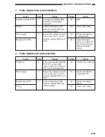
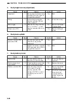
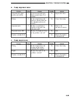
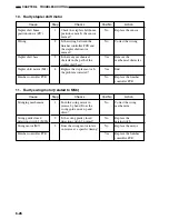
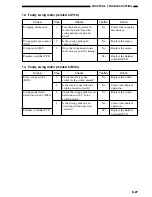
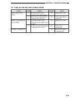
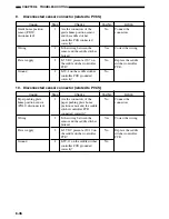
14. Faulty swing motor (related to PI20)
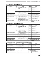
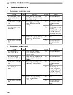
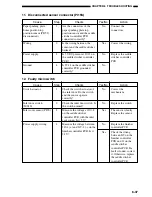
15. Faulty tray-1 lift motor (related to PI8)
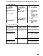
16. Faulty tray-2 lift motor (related to PI25)
Checks
Check the swing motor clock
sensor. Is the sensor normal?
Does the voltage of the swing
motor between J11-6 and -7
on the finisher controller PCB
reach 24 V at a specific
rotation timing?
Cause
Swing motor clock
sensor (PI20)
Finisher controller PCB
Step
1
2
Yes/No
No
No
Yes
Action
Replace the sensor.
Replace the finisher
controller PCB.
Check the wiring from
the motor to the
finisher controller
PCB. If normal,
replace the motor.
Checks
Check the tray-1 home
position sensor. Is it normal?
Check the tray-1 lift
mechanism. Is the mechanism
normal?
Is the tray-1 lift motor
supplied with 24 VDC by the
finisher controller PCB as
soon as the tray is driven?
Check the wiring from the
finisher controller PCB to the
tray-1 lift motor. Is the wiring
normal?
Cause
Tray-1 home position
sensor (PI8)
Tray-1 lift mechanism
Finisher controller PCB
Wiring
Tray-1 lift motor (M5)
Step
1
2
3
4
Yes/No
No
No
No
No
Yes
Action
Replace the sensor.
Correct the
mechanism.
Replace the finisher
controller PCB.
Correct the wiring.
Replace the tray-1 lift
motor.
Checks
Check the tray-2 lift
mechanism. Is the mechanism
normal?
Is the tray-2 lift motor
supplied with 24 VDC by the
finisher controller PCB as
soon as the tray is driven?
Check the wiring from the
finisher controller PCB to the
tray-2 lift motor. Is the wiring
normal?
Cause
Tray-2 lift mechanism
(PI25)
Finisher controller PCB
Wiring
Tray-2 lift motor (M10)
Step
1
2
3
Yes/No
No
No
No
Yes
Action
Correct the
mechanism.
Replace the finisher
controller PCB.
Correct the wiring.
Replace the tray-2 lift
motor.
Note :
If the tray cannot be lowered because it makes contact with something under the Finisher, this error occurs.
Therefore, tell the users not to place anything under the tray.
Содержание MJ-1027
Страница 1: ...SERVICE MANUAL FINISHER MJ 1027 1028 File No SME040041A0 R04102169300 TTEC Ver01_2007 09 ...
Страница 5: ...ii ...
Страница 9: ...vi ...
Страница 70: ...2 41 CHAPTER 2 FINISHER UNIT BASIC OPERATION Height sensor PS1 Paper Figure 2 240 ...
Страница 101: ...3 15 CHAPTER 3 SADDLE STITCHER UNIT BASIC OPERATION Figure 3 301 ...
Страница 104: ...3 18 CHAPTER 3 SADDLE STITCHER UNIT BASIC OPERATION 2 A3 LD Paper Path 3 sheets Figure 3 303 ...
Страница 116: ...3 30 CHAPTER 3 SADDLE STITCHER UNIT BASIC OPERATION Cam Mount Figure 3 404 ...
Страница 150: ...4 20 CHAPTER 4 MECHANICAL CONSTRUCTION 7 Remove the tension springs front 5 rear 6 Figure 4 216 Figure 4 217 5 6 ...
Страница 173: ...6 CHAPTER 6 TROUBLESHOOTING II ARRANGEMENT OF ELECTRICAL PARTS A Finisher Unit ...
Страница 235: ...2 17 2 HIGASHIGOTANDA SHINAGAWA KU TOKYO 141 8664 JAPAN ...

