3-4
CHAPTER 3 SADDLE STITCHER UNIT BASIC OPERATION
2.
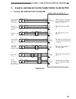
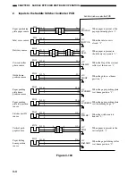
Inputs to the Saddle Stitcher Controller PCB
PI8S
J105-3
-1
-2
-1
-3
-2
-3
-1
-2
J6-1
+5V
When paper is present at the
paper positioning plate, “1”.
PPOSPAR
-3
-2
J301A
J225
J425
J301
J201
PI9S
J124-3
-1
-2
J10-6
+5V
When the inlet cover is
closed, “1”.
INLTCVR
-8
-7
PI11S
J525-3
-1
-2
-2
-4
-3
-3
-1
-2
J9-1
+5V
When paper is present in
the delivery sensor unit, “1”.
DELV
-3
-2
J425
J325
-2
-4
-3
-3
-1
-2
J225
J125
PI12S
J126-3
-1
-2
J9-4
+5V
When the flag of the crescent
roller is at the sensor, “1”.
FDRLHP
-6
-5
PI13S
J127-3
-1
-2
J9-7
+5V
When the guide is at home
position, “1”.
GIDHP
-9
-8
PI14S
J128-3
-1
-2
J9-10
+5V
When the paper pushing plate
is at home position, “1”.
LUNGEHP
-12
-11
PI15S
J129-3
-1
-2
J9-13
+5V
When the paper pushing plate
is at the leading edge, “1”.
LUNGETOP
-15
-14
PI16S
J131-3
-1
-2
J13-1
+5V
When the stitcher unit is
housed, “0”.
STPLHP*
-3
-2
PI17S
J132-3
-1
-2
-1
-3
-2
-4
-2
-3
J13-4
+5V
When paper is present in the
vertical path, “1”.
When the paper folding roller
is at home position, “0”.
VPJM
-6
-5
J308A
J308
J208
PI21S
J130-3
-2
-1
J18-1
+5V
PAFLDHP*
-3
-2
Saddle stitcher controller PCB
Paper positioning
plate paper sensor
Inlet cover sensor
Delivery sensor
Crescent roller
phase sensor
Guide home
position sensor
Paper pushing
plate home
position sensor
Paper pushing
plate top position
sensor
Stitcher unit IN
sensor
Vertical path
paper sensor
Paper folding
home position
sensor
Figure 3-104
Содержание MJ-1027
Страница 1: ...SERVICE MANUAL FINISHER MJ 1027 1028 File No SME040041A0 R04102169300 TTEC Ver01_2007 09 ...
Страница 5: ...ii ...
Страница 9: ...vi ...
Страница 70: ...2 41 CHAPTER 2 FINISHER UNIT BASIC OPERATION Height sensor PS1 Paper Figure 2 240 ...
Страница 101: ...3 15 CHAPTER 3 SADDLE STITCHER UNIT BASIC OPERATION Figure 3 301 ...
Страница 104: ...3 18 CHAPTER 3 SADDLE STITCHER UNIT BASIC OPERATION 2 A3 LD Paper Path 3 sheets Figure 3 303 ...
Страница 116: ...3 30 CHAPTER 3 SADDLE STITCHER UNIT BASIC OPERATION Cam Mount Figure 3 404 ...
Страница 150: ...4 20 CHAPTER 4 MECHANICAL CONSTRUCTION 7 Remove the tension springs front 5 rear 6 Figure 4 216 Figure 4 217 5 6 ...
Страница 173: ...6 CHAPTER 6 TROUBLESHOOTING II ARRANGEMENT OF ELECTRICAL PARTS A Finisher Unit ...
Страница 235: ...2 17 2 HIGASHIGOTANDA SHINAGAWA KU TOKYO 141 8664 JAPAN ...

