4-23
CHAPTER 4 MECHANICAL CONSTRUCTION
4.
Removing the Stitcher Mount Unit
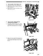
1) Remove the front inside cover (see II-A-3).
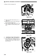
2) Remove the E-ring [1], and remove the roll
[2] and the shaft [3].
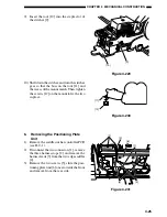
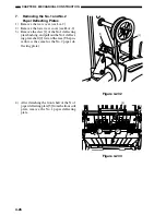
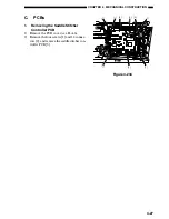
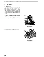
Figure 4-223
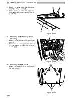
Figure 4-225
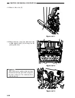
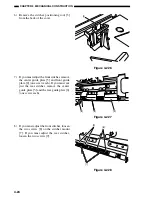
3) Pull out the stitcher mount unit [4] to the
front.
Figure 4-224
5.
Adjusting the Stitcher Position
1) Remove the front lower door (see II-A-1).
2) Remove the front inside cover (see II-A-3).
3) Open the front door assembly.
4) Pull out the stitcher mount unit to the front,
then pull out the stitcher towards you and
then pull the stitcher down.
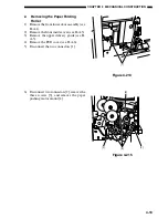
5) Remove the three screws [1], and remove
the stitcher mount unit cover [2].
[1]
[2]
[3]
[4]
[1]
[2]
Содержание MJ-1027
Страница 1: ...SERVICE MANUAL FINISHER MJ 1027 1028 File No SME040041A0 R04102169300 TTEC Ver01_2007 09 ...
Страница 5: ...ii ...
Страница 9: ...vi ...
Страница 70: ...2 41 CHAPTER 2 FINISHER UNIT BASIC OPERATION Height sensor PS1 Paper Figure 2 240 ...
Страница 101: ...3 15 CHAPTER 3 SADDLE STITCHER UNIT BASIC OPERATION Figure 3 301 ...
Страница 104: ...3 18 CHAPTER 3 SADDLE STITCHER UNIT BASIC OPERATION 2 A3 LD Paper Path 3 sheets Figure 3 303 ...
Страница 116: ...3 30 CHAPTER 3 SADDLE STITCHER UNIT BASIC OPERATION Cam Mount Figure 3 404 ...
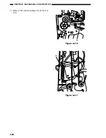
Страница 150: ...4 20 CHAPTER 4 MECHANICAL CONSTRUCTION 7 Remove the tension springs front 5 rear 6 Figure 4 216 Figure 4 217 5 6 ...
Страница 173: ...6 CHAPTER 6 TROUBLESHOOTING II ARRANGEMENT OF ELECTRICAL PARTS A Finisher Unit ...
Страница 235: ...2 17 2 HIGASHIGOTANDA SHINAGAWA KU TOKYO 141 8664 JAPAN ...

