18-9
18 CHECKS AND ADJUSTMENTS
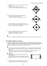
4) Turn the upper part of the instrument horizontally through
180° and note the new position (y) of the laser beam.
Adjustment will bring the laser beam to a point midway
along a line drawn between these two positions.
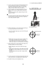
5) Check the position of the desired final position. Place a
target so that its center is aligned with the desired final
position.
The remaining deviation will be adjusted using the 4 fine
adjustment screws.
•
Be extremely careful to adjust all the fine adjustment screws
by the same amount so that none will be over-tightened.
•
Turn screws clockwise to tighten.
6) When the laser beam is on the upper (lower) part of Fig. A
the up/down adjustment is made as follows:
a. Insert the provided hexagon key wrench into both the upper
and lower screws.
b. Slightly loosen the upper (lower) screw and tighten the
lower (upper) screw. Make sure that the tightening
tension for both screws is identical. Continue to adjust
until the laser beam is on the horizontal line of the target.
7) When the laser beam is in the right (left) part of Fig. B the
left (right) adjustment is made as follows:
a. Insert a hexagon key wrench into both the left and right
screws.
b. Slightly loosen the right (left) screw and tighten the left (right)
screw. Make sure that the tightening tension for both screws
is identical.
Continue to adjust until the laser beam is aligned with the
target center.
8) Turn the upper part of the instrument horizontally and check
that the laser beam is now aligned with the target center.
9) Re-attach the laser plummet adjustment cap.
x
y
Desired final position
Target
Fine adjustment screws
Fig. A
Desired final position
Fig. B


