26
Final Connections
A Note on Cable Routing
When routing cables, you will want to adhere to a few guidelines;
•Keep data cables and power cables separate.
•Keep cables away from dust collection systems.
•Keep cables away from florescent lighting.
•Keep data cables away from any electrical noise generating devices.
•Do not overtighten any zip ties or other cable management restraints.
•Ensure all cables are routed so that they will not become crushed or pinched.
TigerStop Amp and Controller Connections
1. Ensure TigerStop is powered off.
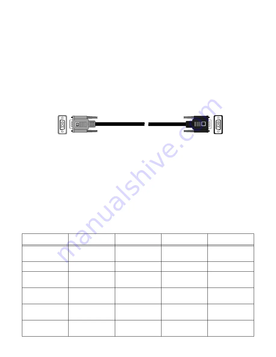
2. You will have two controller cables. Locate the first controller cable.
3. Plug the silver end of one controller cable into the I/O panel plug labeled “Controller”.
4. Plug the opposite end of this controller cable (black) into the TigerStop controller.
5. Locate the second controller cable.
6. Plug the black end of this cable into the I/O panel port labeled “Amp”.
7. Plug the opposite end of this cable (silver) into the TigerStop motor box.
Mount Controller to Controller Stand
The TigerSaw Guard will come from the factory with the controller stand already attached. Slide the
controller on to the stand and tighten the supplied bolts to hold it in place.
Note: Do not over tighten!
Input/Output Connections
TigerSaw has many connections to the I/O panel input and output plugs. Many of these are con-
nected from the factory. Use the chart below to make the final I/O panel connections.
I/O Plug
Goes To
Cable Color
Number of Pins
Cable Label
Interlock In
TigerStop Motor
Box
Gray
6
Int In
E-Stop
Saw Control Box
Brown
4
EStop
Tool At Extension
(TA)
Top Arbor Sensor
Gray
4
Tool Ext
Cycle Start
(Edge Detect)
Pusher Foot
Gray
4
Edge
Tool At Rest
(UV Det)
Pusher Foot
Yellow
4
UV Det
Tool Out
(SE)
Pneumatic Valve
inside saw
Gray
4
T out
Содержание TigerSaw 1000
Страница 1: ......
Страница 2: ......
Страница 8: ...5 TigerSaw Cap Guard TigerSaw Guard Back ...
Страница 9: ...6 TigerSaw Guard Sides ...
Страница 10: ...7 TigerSaw Blade Access Door In Feed and Out Feed Table ...
Страница 11: ...8 Pusher Foot ...
Страница 15: ...12 1 Assemble table legs ...
Страница 17: ...14 5 Attach the back fence to the out feed table 6 Attach the material staging tubes to the in feed table ...
Страница 24: ...21 7 Attach the Printer Stand M8 X 35 ...
Страница 66: ......
Страница 67: ......


