


Operating Instructions
6-14
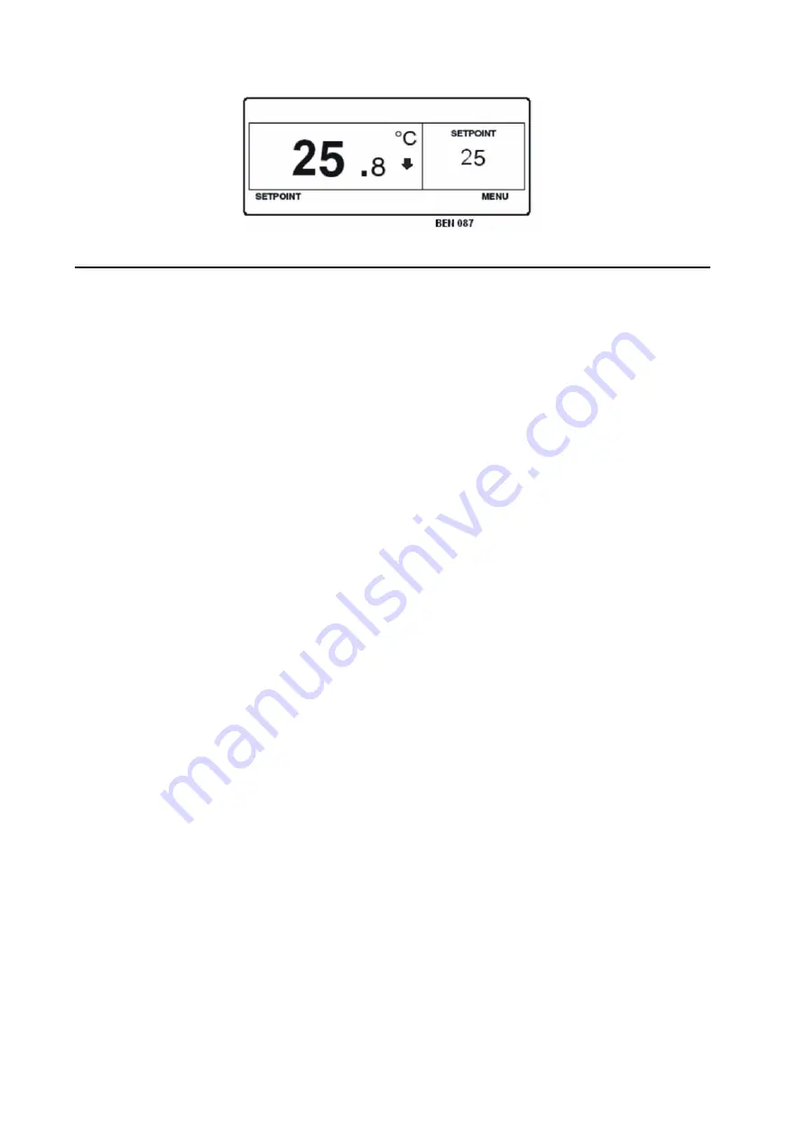
Single Zone Standard Display
Operating The Unit In Single Zone Control Mode
There are two methods of operating the unit in Single Zone Control.
Method 1:
The unit may be operated with each Zone individually set to the same setpoint temperature. For example, each Zone could be
individually set to 35 C. The evaporator in each compartment will then control the temperature in that compartment to the same
35 C setpoint.
NOTE: Using Method 1, it is recommended that the bulkheads that separate each compartment be in place to isolate the
compartments.
Method 2:
If Single Zone Control Mode has been has been enabled in the Guarded Access/Main Menu Configuration menu, the following
will apply.
• Single Zone Control Mode will appear in the Mode Menu only if the Single Zone Control feature has been enabled in the
Guarded Access/Main Menu Configuration menu. IF the feature is enabled then Single Zone Control will appear in the Main
Menu/Mode Menu.
• If Single Zone Control operation is selected then all zones will be forced on and will control to the same setpoint. The Zone
1 sensors are used to determine box temperature.
NOTE: Using Method 2, it is recommended that all bulkheads should be taken down to create one large compartment.
• With the exception of defrost, the operating mode of each zone evaporator(s) will be same when in this mode. Unit control is
based on the temperature sensors of Zone 1.
• If Single Zone Control operation is selected the Single Zone Standard Display provides one soft key labeled Setpoint as shown
in Figure . This allows the setpoint for all zones to be changed simultaneously.
• If Single Zone Control operation is selected the individual zones cannot be turned off. The unit and all zones are turned On
and Off simultaneously using the On and Off hard keys at the left side of the display.
NOTE: If Single Zone Control Mode has been enabled in the Guarded Access/Main Menu Configuration menu, either Single
Zone or Multi Zone control can be selected in the Main Menu/Mode menu. For example, to return to Multi Zone Control
from Single Zone Control, select Multi Zone Control in the Main Menu/Mode menu.
NOTE: When using Single Zone Control Mode on SLX units equipped with ETV (SLX Spectrum ETV, SLXe Spectrum and
SLXi Spectrum) the modulation function is disabled.
Содержание SLXi Spectrum
Страница 17: ...Safety Precautions 2 5 Warning Decals...
Страница 18: ...Safety Precautions 2 6 Warning Decals Information Decals...
Страница 74: ...Unit Description 5 30...
Страница 128: ...Controller Operation 7 28...
Страница 156: ...Electrical Maintenance 8 28...
Страница 177: ...Engine Maintenance 9 21 Integral Fuel Solenoid Components 1 Integral Fuel Solenoid 2 O ring 3 Fuel Injection Pump Groove...
Страница 234: ...Refrigeration Maintenance 10 22...
Страница 309: ...13 Mechanical Diagnosis TK 482 TK 486 and TK 486V Engines 13 2...
Страница 316: ...Mechanical Diagnosis 13 8...
Страница 322: ...Refrigeration System Diagnosis 14 6...
Страница 332: ...Single Temperature Refrigeration System Diagrams 15 10...
Страница 339: ...Multi Temperature Refrigeration System Diagrams 16 7...
Страница 340: ...Multi Temperature Refrigeration System Diagrams 16 8...
Страница 342: ...Wiring Diagrams and Wiring Schematics 17 2...


