Electrical Maintenance
8-10
Strator
T
he stator assembly consists of three individual windings terminated in the delta-type connections. Using an ohmmeter or test
lamp, check for winding continuity between leads A, B, and C. There should be no continuity from any lead to point D
(laminations). Also, stators showing signs of winding discolouration should be discarded
Diode Plate Assembly
The diode plate assembly consists of two plates, each containing three diodes. Both plates are mounted on a plastic insulator thus
making a diode plate assembly. The plate with the B+ terminal contains the positive diodes and the other plate contains the
negative diodes. When testing the diodes, the positive and negative diodes are tested separately.
Using an ohmmeter or diode tester, check for continuity as follows:
1. Place the negative lead of the meter on G. Place the positive lead of the meter on A, B, and C. There should be continuity
from G to A, B, and C.
2. Place the positive lead of the meter on G. Place the negative lead of the meter on A, B, and C. There should be no continuity
from G to A, B, or C.
3. Place the positive lead of the meter on H. Place the negative lead of the meter on D, E, and F. There should be continuity from
H to D, E, and F.
4. Place the negative lead of the meter on H. Place the positive lead of the meter on D, E, and F. There should be no continuity
from H to D, E, or F.
Alternator Assembly
1. Connect the stator windings to the diode plate.
Solder the three leads of the stator windings to the diode plate if either is to be replaced.
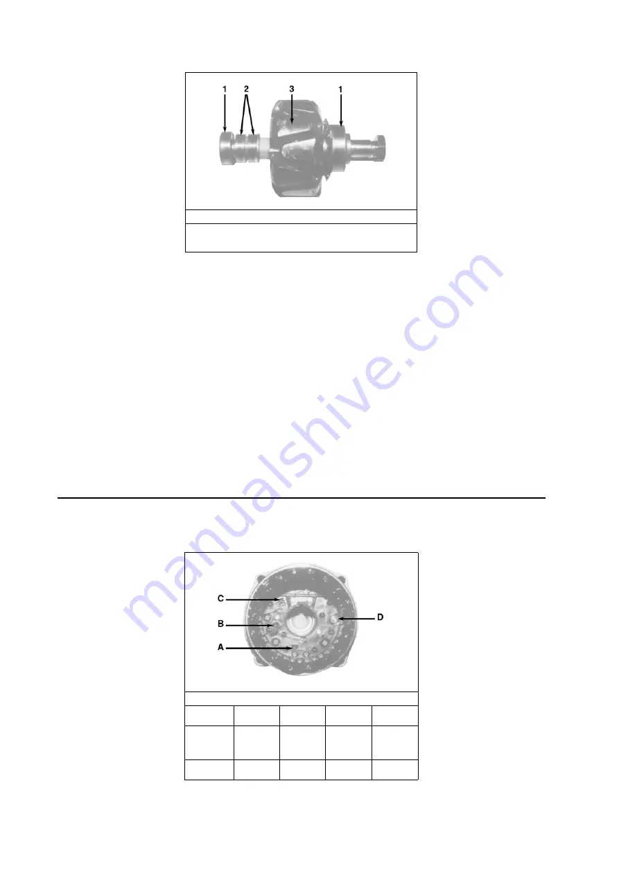
Rotor
1.
Bearings (2)
2.
Slip Rings
3.
Pole Fingers (Rotor Body)
Testing Stator — Stator Resistance Values
Alternator
A to B
A to C
B to C
A, B, C to
D
23 amps
37 amp
65 amp
.21 ohm*
.32 ohm**
.11 ohm**
.21 ohm*
.32 ohm**
.11 ohm**
.21 ohm*
.32 ohm**
.11 ohm**
None
None
None
*20.0°C
**25.0°C
Содержание SLXi Spectrum
Страница 17: ...Safety Precautions 2 5 Warning Decals...
Страница 18: ...Safety Precautions 2 6 Warning Decals Information Decals...
Страница 74: ...Unit Description 5 30...
Страница 128: ...Controller Operation 7 28...
Страница 156: ...Electrical Maintenance 8 28...
Страница 177: ...Engine Maintenance 9 21 Integral Fuel Solenoid Components 1 Integral Fuel Solenoid 2 O ring 3 Fuel Injection Pump Groove...
Страница 234: ...Refrigeration Maintenance 10 22...
Страница 309: ...13 Mechanical Diagnosis TK 482 TK 486 and TK 486V Engines 13 2...
Страница 316: ...Mechanical Diagnosis 13 8...
Страница 322: ...Refrigeration System Diagnosis 14 6...
Страница 332: ...Single Temperature Refrigeration System Diagrams 15 10...
Страница 339: ...Multi Temperature Refrigeration System Diagrams 16 7...
Страница 340: ...Multi Temperature Refrigeration System Diagrams 16 8...
Страница 342: ...Wiring Diagrams and Wiring Schematics 17 2...


