Refrigeration Maintenance
10-19
3. Install a service gauge manifold set on compressor.
4. Front seat the receiver tank outlet valve.
5. Operate the unit on cooling and pump down the low side to -0.68 bar, 20 in. Hg vacuum.
6. Stop the unit. The condenser and suction pressures should remain stable, indicating no leaks.
7. Shift the three-way valve to HEAT position. Low side gauge will raise slightly. High side gauge will decrease to
approximately zero. Gauges will equalise.
8. Gauges will remain in this position (approximately zero) if the three-way valve seals properly toward the condenser and the
condenser pressure bypass check valve seals properly.
9. Gently turn the check valve stem out until the condenser bypass check valve is back seated against the circlip. Both gauges
should rise indicating the condenser pressure bypass check valve is properly releasing condenser pressure into the discharge
tube and evaporator.
10. Replace the cap on the condenser pressure bypass check valve.
NOTE: Valve stem MUST be back seated during normal unit operation.
11. Back seat the receiver tank outlet valve, remove the gauges and return the unit to normal operation.
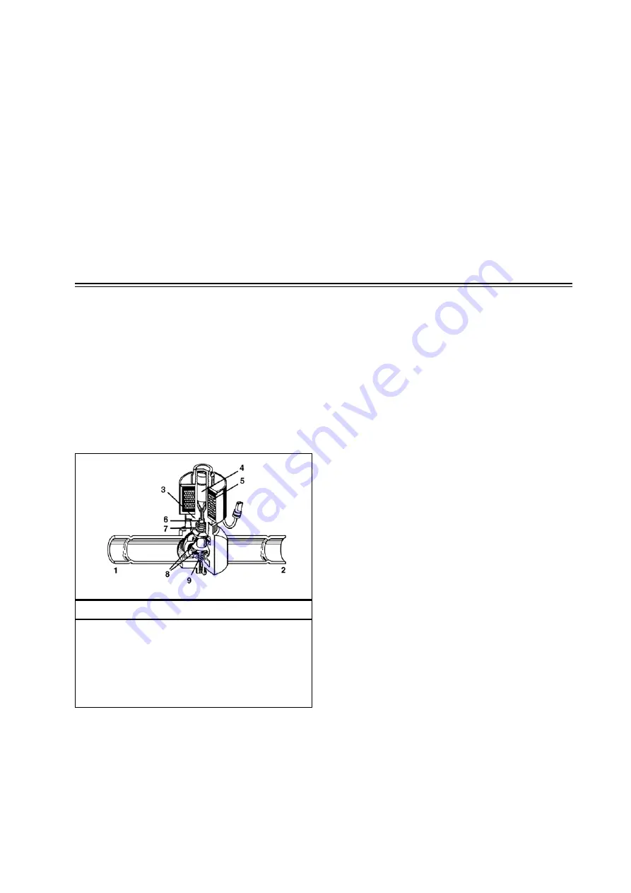
MODULATION VALVE
The modulation valve is normally open. As a controlled electrical signal is applied to the coil, the armature overcomes the spring
tension and the valve closes a precise amount. As the signal strength is increased, the valve closes more. This controls the flow
of suction gas to the compressor. The unit controller (TG-VI or µP-IV) controls the signal and the position of the modulation
valve.
Because of the valve and seat design, the pressure from the flow of fluid past the valve has no opening or closing force on the
valve spool. This allows the valve to provide very precise control of unit cooling capacity.
Service of the valve includes replacement of the coil or replacement of the complete valve.
TG-VI, µP-IV AND µP-V NOTE: See the appropriate Controller Operation and Diagnosis manual for instructions on testing
the modulation valve.
Modulation Valve
1.
Outlet
2.
Inlet
3.
Enclosure Tube
4.
Armature
5.
Electric Coil
6.
Piston
7.
Closing Spring
8.
Valve Seats
9.
Opening Spring
Содержание SLXi Spectrum
Страница 17: ...Safety Precautions 2 5 Warning Decals...
Страница 18: ...Safety Precautions 2 6 Warning Decals Information Decals...
Страница 74: ...Unit Description 5 30...
Страница 128: ...Controller Operation 7 28...
Страница 156: ...Electrical Maintenance 8 28...
Страница 177: ...Engine Maintenance 9 21 Integral Fuel Solenoid Components 1 Integral Fuel Solenoid 2 O ring 3 Fuel Injection Pump Groove...
Страница 234: ...Refrigeration Maintenance 10 22...
Страница 309: ...13 Mechanical Diagnosis TK 482 TK 486 and TK 486V Engines 13 2...
Страница 316: ...Mechanical Diagnosis 13 8...
Страница 322: ...Refrigeration System Diagnosis 14 6...
Страница 332: ...Single Temperature Refrigeration System Diagrams 15 10...
Страница 339: ...Multi Temperature Refrigeration System Diagrams 16 7...
Страница 340: ...Multi Temperature Refrigeration System Diagrams 16 8...
Страница 342: ...Wiring Diagrams and Wiring Schematics 17 2...


