


Page 9
6/23/04 DI-50B51 320 Series (NZ306)
Texmate, Inc. Tel. (760) 598-9899
•
www.texmate.com
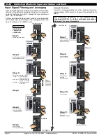
B
l
o
ck
D
i
a
g
r
a
m
o
f
t
h
e
T
i
g
e
r
320
So
f
t
w
a
r
e
a
nd
H
a
r
d
w
a
r
e
St
r
u
c
t
u
r
e
RESIDENT TIMER 1
RESIDENT TIMER 2
Runs ONLY if selected on CH3,
or CH4. Resolution 1 sec
I2C
BUS
LOGIC I/O
FROM
MODULES
Prescaler
Channel 1 & 2
17 BIT ON BOARD
DUAL SLOPE A to D
REF IN
CHANNELS
RESULT
CHANNEL
1
2
3
4
CHANNELS 1
2
1
2
3
4
1
R
R
2
3
4
1
R
D
D
2
3
4
1
R
DEFAULT
DISPLAY
CHANNEL
DEFAULT
DISPLAY
CHANNEL
2
3
4
DISPLAY FORMATTING
I2C
MICRO
Sigma Delta
A to D
16 to 24 Bit
Signal
Conditioning
REF
SSR
SSR
REF
Sig
Con
SMART MODULES WITH MULTICHANNEL INPUTS,
AN ON-BOARD A TO D CONVERTER,
MICROPROCESSOR, AND TWO
SOLID STATE RELAY OUTPUTS
Signal
Conditioning
MULTI-INPUT MODULES
W/DIGITAL SCALING
MUX
REF
PULSE
Signal
Conditioning
SINGLE INPUT MODULES
WITH ANALOG SCALING
REF
ZERO
SPAN
Signal
Conditioning
REF
12-30-02 4:00 PM
RAW DATA
ANALOG, DIGITAL
AND LOGIC I/O
MACRO PROCESSING
A macro can access all functions and read
and write into all registers. Macro Timer1,
Macro Timer2 have 0.1 second resolution.
Macros allow a user to customize the meter
for a specific application using the Tiger 320
Development system.
Macros may be locked to prevent access by
anyone.
DATA LOGGING
Manual or auto, Up to 4000
samples, Date and Time
stamp, endless loop record,
Burst downloading
SERIAL COMMUNICATION
Read and write into all registers
ASCII, MODBUS, DEVICENET
Meter TO Meter Communication,
ETHERNET (TCP/IP), Epson Compatible
Serial Printer Driver
SETPOINTS
Up to 6 relay, SSR,
TTL or open collector.
PID, deviation, trigger, pulse,
tracking, hysteresis, latching,
timer modes, reset,
High/low/deviation activation
TOTALIZER 1
TOTALIZER 2
Two independent totalizers
Linearizing
4 Tables of 32 Points each
or 1 Table of 125 Points
Internal System Clock
Downloads from Real Time Clock
or starts from 12:00 on power up.
Can be displayed on CH3, CH4
Optional Real-time clock
with date and time stamp
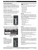
Rear Pins
Hold, Test, Lock & Capture.
The Lock, Hold and Capture
pins can be reprogrammed
for use as Digital Logic I/O pins.
ANALOG OUTPUT
Voltage or current,
single or dual
PLUG IN OPTO-ISOLATED
I/O 6 IN 6 OUT OR 6 IN 16 OUT
DISPLAY DRIVE
SMART MODULES WITH AN ON BOARD
MICROPROCESSOR AND TWO SOLID STATE
RELAY OUTPUTS WITH PULSE, OR QUADRATURE
ENCODER INPUTS FOR COUNTING, FREQUENCY OR POSITION
I2C
MICRO
Signal
Conditioning
SSR
SSR
REF
Sig
Con
Signal
Conditioning
Cross Channel Math
1+2, 1-2, 1x2, 1/2, 1=R
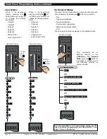
RESET
with UP/DOWN
Peak, Valley,
Tare, Totalizers
VIEW MODE
to view
selected
function values
P and UP Buttons
to enter setup
menu.
P and DOWN
Buttons to enter
setpoint menu.
PROGRAM
BUTTON
MACRO_
PROCESSING
Including
EDIT MACRO
F1_BUTTON
MACRO_
PROCESSING
F2_BUTTON
MACRO_
PROCESSING
F3_BUTTON
MACRO_
PROCESSING
ON DEMAND
FUNCTIONS
Hold down the
PROGRAM
button for 4 secs
to initiate Auto
tare, Auto
Calibration,
Manual Loader or
Input Channel
Compensation
PROGRAM LOCK
If Program lock is ON values are
displayed, but cannot be changed
SETPOINT LOCK
If Program lock is ON values are
displayed, but cannot be changed
Prog
F1
F2
F3
RESULT PROCESSING
of Cross Channel Math
Select data source for
OUTPUT PROCESSING
Select data source for: Setpoint 1, 2, 3, 4, 5, 6;
Analog output 1, 2; Data logging
Select data source for
DISPLAY PROCESSING
Select data source for:
Display 1 (Default Display Channel D), Display 2,
Display 3, Peak, Valley, Totalizer 1, Totalizer 2,
AVERAGING,
CALIBRATION (SCALE and OFFSET),
INVERSE OF INPUT, LINEARIZATION,
LOG OF INPUT (Bargraph display only)
RTD, SAMPLE RATE, SMART AUTO ZERO,
SQUARE ROOT, THERMOCOUPLES
DECIMALS, , RIGHT HAND CHARACTER, AND ROUNDING
FOR CH1, 2, 3, 4, RESULT AND DEFAULT DISPLAY
CUSTOM TEXT FOR CH1, 2, 3, 4, RESULT, PEAK, VALLEY,
TOTALIZER 1, TOTALIZER 2, SP1, SP2, SP3, SP4, SP5, SP6
DIGITAL PROCESSING
Select from R, 1, 2, 3, 4, Totalizer 1, 2, Peak,
Valley, Tare or any usable registers from 1 to 244
Select from R, 1, 2, 3, 4, Totalizer 1, 2, Peak,
Valley, Tare or any usable registers from 1 to 244
Code1
SPC_1 to 6
SPC_1 to 6
Code1
Code7
Code2
Code4
Code5
Code6
Code8
CAL
CAL
CAL
CAL
CAL
CAL
CAL
CAL
Linearization
24 bit registers in EEPROM that store
the four 32 point LIN tables.
Registers 257 to 512
OPERATING SYSTEM USE ONLY
DO NOT write to these registers, as
any alteration to their data may make
the meter inoperative.
Registers 1125 to 2048
OPERATING SYSTEM USE ONLY
DO NOT write to these registers, as
any alteration to their data may make
the meter inoperative.
Registers 4097 to 5120
Multi function, multi type Registers
that may only be accessed through
the serial port or by macros. Their
functions are detailed in the Register
Supplement.
Registers 513 to 1124
Macro Code Storage
16 bit unsigned. In Flash RAM
Registers 2049 to 4096
16 bit unsigned. May be
accessed by macros or
Serial Port.
Registers 5120 to 6144
Code9
Code5
Code6
FLASH
Result of Cross
Channel Math
AVERAGING, CALIBRATION (SCALE & OFFSET),
INVERSE of R, LOG OF R (Bargraph display only)
LINEARIZING of R,
SMART AUTO ZERO,
SQUARE ROOT of R,
SP1
SP2
SP3
SP4
SP5
SP6
Registers 1 to 244
Registers from 1 to 244 may be selected
manually as a data source for setpoint
or output processing. However only
those registers shown below contain
data applicable for use as data source.
Setpoints
6 to 11- SP1,2,3,4,5,6 value
65 to 70- SP1,2,3,4,5,6 Hysteresis,
71 to 76- delay on make SP1,2,3,4,5,6
77 to 82- delay on break SP1,2,3,4,5,6
Input Channels
18,19,20,41,42- Raw Result,CH1,2,3,4
21 to 23,43,44- Scaled Result,CH1,2,3,4
45,46- Prescaler CH1,2
Smart modules
54 to 60- Smart Output 1,2,3,4,5,6,7
Analog Outputs
83, 84 - Analog Output 1 & 2
Variables (Used with Macro Only)
85 to 94 - Variable 1 to Variable 10
Timers
95 & 96 - Timer 1, 2
Real time Clock
213 to 219 - Real Time Clock
Auto Zero Offset
227 to 231 - Auto Zero Offset for Result,
CH1, CH2, CH3 & CH4
Operating System
NOT USABLE as a data source.
15,38,47,48,52,53,61-64,123-128,140,
141,160,161,234-244
6144 REGISTERS
Registers are comprised of 8, 16 or
32 bit signed, unsigned or floating
point registers, implemented in either
Flash RAM, RAM, FeRAM, EEPROM
or NVRAM (Real time clock option).
See the Register Supplement for
detailed information on ALL registers
All registers may be accessed, and
read or written to via the serial port,
and by user developed macros.
The registers used for the operating
system should not be written into, as
modification of their data may render
the meter inoperative.
LOG BARGRAPH DISPLAY, dB DISPLAY, OCTAL.
BRIGHTNESS, ANNUNCIATORS, TREND
SCALE, OFFSET FOR CH1, 2, 3, 4 AND RESULT


