


Page 39
6/23/04 DI-50B51 320 Series (NZ306)
Texmate, Inc. Tel. (760) 598-9899
•
www.texmate.com
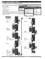
Step 3
Step 1
Operational Display
80
100
90
70
60
50
40
30
20
10
0
SP
SP
6
5
4
3
2
1
Press
at same
time
Press
at same
time
Enter Brightness Mode
80
100
90
70
60
50
40
30
20
10
0
SP
SP
6
5
4
3
2
1
80
100
90
70
60
50
40
30
20
10
0
SP
SP
6
5
4
3
2
1
Press
7
80
100
90
70
60
50
40
30
20
10
0
SP
SP
6
5
4
3
2
1
80
100
90
70
60
50
40
30
20
10
0
SP
SP
6
5
4
3
2
1
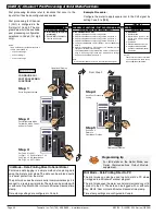
From Step 4
Step 4
Step 5
Exit Code 7.
Return to
Operational Display
Operational Display
80
100
90
70
60
50
40
30
20
10
0
SP
SP
6
5
4
3
2
1
80
100
90
70
60
50
40
30
20
10
0
SP
SP
6
5
4
3
2
1
Press
at same
time
Press
at same
time
80
100
90
70
60
50
40
30
20
10
0
SP
SP
6
5
4
3
2
1
Press
1
X
Step 2
Pass Brightness Mode,
Calibration Mode, and
Codes 1 to 5 and enter
Code 6
Set Code 6 to [01X]:
1st Digit = 2 Selects inverse of CH4
2nd Digit = 1 Selects voltage, current
3rd Digit = X Not relevant
Save CH4 setting
CONFIGURE
CH4 FUNCTIONS
OR
CH4 POST PROCESSING
0 Direct Display of Input (no pro-
cessing)
1 Square Root of Channel 4
2 Inverse of Channel 4
3
4 kB Meters
32-point Linearization of CH4 using
Table 1
32 kB Meters
32-point Linearization of CH4 using
Table 4
Note:
All linearization tables are set up
in the Calibration Mode [24X].
CODE 6
–
CHANNEL 4 FUNCTIONS
FIRST DIGIT
SECOND DIGIT
THIRD DIGIT
FOR THERMOCOUPLE
0 Type J
1 Type K
2 Type R
3 Type S
4 Type T
5 Type B
6 Type N
7 Select user defined linearization
table (Table 1) set up in CAL [24X]
FOR RTD TYPE (2-, 3-, 4- WIRE)
0 Resistance
1 RTD 385
2 RTD 392
3 RTD 120
4 Cn 10
MEASUREMENT TASK
0 No Function
1 Voltage / Current
2 TC (3rd digit selects type of
TC).
See Note 7
3 RTD (3rd digit selects type of
RTD).
See Note
7
4 Real Time Clock and Timer (3rd
digit selects type)
5 -
6 -
7 Smart Input Module (3rd digit
selects register)
FOR SMART INPUT MODULE
0 Output Register 1
1 Output Register 2
2 Output Register 3
3 Output Register 4
4 Output Register 5
5 Output Register 6
6 Output Register 7
7 Smart Input Module Register 3
Code Setup
Note: 7
For future development.
FOR REAL-TIME CLOCK & TIMER
0 HRS:MIN:SEC
1 HRS:MIN
2 -
3 -
4 1 Second Count UP Timer
5 1 Second Count DOWN Timer
6 -
7 -
P
Press
Use the
buttons to set the
required smart input module code
(0 to 377). See
I-Series Input
Modules Guide (Z87)
for code
details.
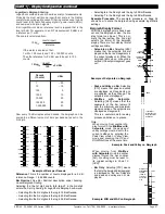
Code 6 is a single code that
combines all the configuration
and post processing functions
available for Channel 4.
When a
quad input
signal
conditioner is installed, the
fourth input signal is processed
and displayed on CH4.
Post processing and measure
ment task functions for CH4 are
configured in the 1st, 2nd, and
3rd digits of Code 6. The
diagram opposite lists the avail-
able configuration selections in
Code 6.
Example Procedure:
Configure CH4 as direct display of voltage input by
setting Code 6 to [
01X
].
ST
ST
AR
AR
T HERE
T HERE
I
n
i
ti
al
S
e
t
up P
r
o
c
e
du
r
e
s
[
C
o
d
E
_
6
]
-
C
h
a
nn
e
l
4
F
un
c
ti
o
n
s
See
I-Series Input Modules Guide (Z87)
for pro-
cedures to set up a quad input module.


