


Texmate, Inc. Tel. (760) 598-9899
•
www.texmate.com
Page 56
6/23/04 DI-50B51 320 Series (NZ306)
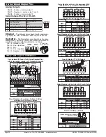
IGYY
: Dual Direct Pressure (Absolute or Differential/Gage)
see below for ordering code options
TIGER
343B
SINGLE or
DIFFERENTIAL
PRESSURE
INPUT
(CH1)
SINGLE or
DIFFERENTIAL
PRESSURE
INPUT
(CH2)
IGYX
: Direct Pressure (Absolute or Differential/Gage)
with 2 Digital Inputs. See below for ordering code options
TIGER
PIN 4
317C
+24 V EXC
GND
Conditioned FREQ / CNTR (CH2)
and STATUS INPUT (D1)
Conditioned STATUS INPUT (D2)
SINGLE or
DIFFERENTIAL
PRESSURE
INPUT
(CH1)
R
E
Q
N
T
R
T
T
L
M
V
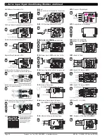
Magnetic Pickup Connected to IF10
TIGER
C
O
U
P
L
IN
G
4
COUNTER UP/DOWN
IN
P
U
T
S
IG
N
A
L
F
IL
T
E
R
C
O
U
N
T
F
R
Q
C
H
2
M
A
G
N
A
M
U
R
S
O
U
R
C
E
S
IN
K
L
O
A
D
AC
20KHz
2KHz
200Hz
OFF
DC
MAG/AC
LOGIC
GND
+24V
Shield
Shield
INPUT
High Accuracy Digital Measurement
Magnetic
Pickup
(Always use shielded wire)
g
330B
Switch or Dry Contact Connected to IF10
TIGER
C
O
U
P
L
IN
G
4
COUNTER UP/DOWN
IN
P
U
T
S
IG
N
A
L
F
IL
T
E
R
C
O
U
N
T
F
R
Q
C
H
2
M
A
G
N
A
M
U
R
S
O
U
R
C
E
S
IN
K
L
O
A
D
AC
20KHz
2KHz
200Hz
OFF
DC
MAG/AC
LOGIC
GND
+24V
INPUT
High Accuracy Digital Measurement
Switch or
Dry Contact
When switch is open, Pin 1 is at 24V
When switch is closed, Pin 1 goes to 0V
f
330B
IGYZ
: Universal Direct Pressure (Absolute or Differential/Gage)
See below for ordering code options
332D
ABSOLUTE / DIFFERENTIAL
PRESSURE
LEOPARD
TIGER
LYNX
24V
Exc
IP07:
Universal Process Input
2V/5V/
10V
/20V/200V/2mA/20mA/Custom
Custom
2mA
20mA
200V
20V
10V
5V
2V
V
O
LT
A
G
E
C
U
R
R
E
N
T
UNIVERSAL PROCESS
Process input
Requires Digital Calibration
HI
LO
OFF ON
24V EXC
FX-B101Q
TIGER
LEOPARD
LYNX
224C
IP03:
Process Input,
1-5V DC
with Offset, 24V Exc
+24 V
+
_
1 to 5V Input
Offset
0
+
_
< Decrease Zero Increase >
< Decrease Span Increase >
R
a
n
g
e
HI
LO
OFF
ON
2
4
V
E
X
C
LEOPARD
IPO7
LYNX
TIGER
IP07
Fully User Scalable
PROCESS 1 to 5V DC
PIN 2
Common
1 to 5V
250
Ω
4/20mA
091E
IP06:
Process Loop, 4-20mA w/24VDC Exc and Autocal
TIGER
O
F
F
O
N
2
4
V
E
X
C
C
u
s
to
m
2
m
A
2
0
m
A
2
0
0
V
2
0
V
10V
5V
2
V
V
O
LT
A
G
E
C
U
R
R
E
N
T
UNIVERSAL PROCESS
24V Exc
N.O.
N.O.
AUTOCAL
Other devices can be
added to the loop.
Fully User Scalable
224D
IP01:
Process Loop,
4-20mA
IP02:
Process Loop,
4-20mA
with 24VDC EXC
24V
External
Loop Supply
Common
Offset
0
+
_
Other devices can be
added to the loop.
< Decrease Zero Increase >
< Decrease Span Increase >
R
a
n
g
e
HI
LO
OFF
ON
2
4
V
E
X
C
LEOPARD
LYNX
TIGER
Fully User Scalable
PIN 2
+
_
091E
IOR1
: ORP (Oxidation Reduction Potential)
TIGER
ORP
ORP Probe
BNC
Connector
144D
IP08:
Universal Process Input with Autocal
2V/5V/
10V
/20V/200V/2mA/20mA/Custom
O
F
F
O
N
2
4
V
E
X
C
Custom
2mA
20mA
200V
20V
10V
5V
2V
V
O
LT
A
G
E
C
U
R
R
E
N
T
UNIVERSAL PROCESS
Process input
HI
LO
24V
Exc
N.O.
N.O.
AUTOCAL
TIGER
224D
CH2
100
Ω
Pt RTD
CH1
CH1
CH2
C
H
3
C
H
4
2 Wire
4 Wire
100
Ω
Pt RTD
CH4
100
Ω
Pt RTD
All four RTDs
must
be connected for the meter to work.
CH3
100
Ω
Pt RTD
IQT2:
Quad RTD Platinum 100
Ω
RTD
2 Wire Connection
TIGER
236C
3
1
5
15
7
17
9
11
13
4
2
6
16
8
18
10
12
14
IPT1
: Prototype Board for Custom Design
LEOPARD
LYNX
TIGER
195C
IP10
: P 3 Digital Inputs
TIGER
314D
PIN 1
PIN 2
PIN 3
PIN 4
PIN 5
PIN 6
PIN 7
PIN 8
+
+ 24 V EXC 1
+ INPUT 1
2
V
5
V
1
0
V
2
0
V
C
S
T
M
2
m
A
2
0
m
A
C
S
T
M
S
IN
K
S
R
C
E
O
N
O
F
F
O
N
O
F
F
O
N
O
F
F
COUNT
FREQ
FILTER
–
INPUT 1
+ 24 V EXC
GND
STATUS D2
COUNTER / FREQ / STATUS D1
CH1
PROCESS INPUT
20 / 10 / 5 / 2 V
OR
2 / 20 mA
COUNTER / FREQ / STATUS D2
IP09
: 4-20mA with External LIN Table Select
< Increase Span Decrease >
4-20mA/W EXT LIN TABLE SELECT
LIN TABLE
Select 2
LIN TABLE
Select 1
Offset
+ 0
–
TIGER
4-20mA
143A
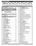
Ordering Code Options for Direct Pressure (IGYX, IGYY & IGYZ)
I
G
For Single Channel IGYX with
two digital inputs, the last digit
of order code is always X.
For Universal Direct Pressure
IGYZ, the last digit of order
code is always Z.
1 psi Absolute
Sensor Range
CH1
Order Code
CH2
Order Code
1 psi Differential
5 psi Absolute
5 psi Differential
15 psi Absolute
15 psi Differential
30 psi Absolute
30 psi Differential
100 psi Absolute
100 psi Differential
A
B
C
D
E
F
G
H
J
K
A
B
C
D
E
F
G
H
J
K
PNP Open Collector Proximity Switch Connected to IF10
TIGER
C
O
U
P
L
IN
G
4
COUNTER UP/DOWN
IN
P
U
T
S
IG
N
A
L
F
IL
T
E
R
C
O
U
N
T
F
R
Q
C
H
2
M
A
G
N
A
M
U
R
S
O
U
R
C
E
S
IN
K
L
O
A
D
AC
20KHz
2KHz
200Hz
OFF
DC
MAG/AC
LOGIC
GND
+24V
INPUT
High Accuracy Digital Measurement
PNP
Open Collector
Proximity Switch
Normally Pin 1 is at 0V
When sensor is activated Pin 1 goes to 24V
e
330B
CH2
100
Ω
Pt RTD
CH1
CH1
CH2
C
H
3
C
H
4
2 Wire
4 Wire
100
Ω
Pt RTD
CH4
100
Ω
Pt RTD
All four RTDs
must
be connected for the meter to work.
CH3
100
Ω
Pt RTD
IQT4:
Quad RTD Platinum 100
Ω
RTD
4 Wire Connection
TIGER
236C
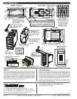
IQT5
: Quad RTD / V / V / FREQ
TIGER
PIN 1
PIN 2
PIN 3
PIN 4
PIN 5
PIN 6
PIN 7
PIN 8
PIN 9
PIN 10
PIN 11
+24 V EXC
GND (AC mV)
FREQ/CNTR INPUT (CH2)
GND (TTL, PNP, NPN)
+ V (CH3)
+V (CH4)
OV (CH4)
OV (CH3)
PT 100
Ω
RTD (CH1)
MV
PNP
TTL
NPN OFF ON FILTER
173F
IR01
: Resistance, 2/
3
/4-Wire, 200
Ω
/
2K
Ω
/20K
Ω
2
0
K
2
K
2
0
0
Ω
RESISTANCE
TIGER
128A
I
I
I
-
S
e
r
i
e
s
I
npu
t
Sig
n
al
C
o
nd
i
ti
o
n
i
n
g
M
o
du
l
e
s
c
o
n
ti
nu
e
d
I
-
S
e
r
i
e
s
I
npu
t
Sig
n
al
C
o
nd
i
ti
o
n
i
n
g
M
o
du
l
e
s
c
o
n
ti
nu
e
d
IH02
: pH with Automatic Temperature Compensation
IH01
: pH
TIGER
pH
Pt-100
Ω
RTD
3 wire
pH Probe
BNC
Connector
Pins 1-3 present
only for IH02
144D
NAMUR Sensor Connected to IF10
TIGER
C
O
U
P
L
IN
G
4
COUNTER UP/DOWN
IN
P
U
T
S
IG
N
A
L
F
IL
T
E
R
C
O
U
N
T
F
R
Q
C
H
2
M
A
G
N
A
M
U
R
S
O
U
R
C
E
S
IN
K
L
O
A
D
AC
20KHz
2KHz
200Hz
OFF
DC
MAG/AC
LOGIC
GND
+24V
INPUT
High Accuracy Digital Measurement
Sensor Resistance is
< 1K
Ω
or > 7K
Ω
Sensor Output is
< 1mA or > 3mA
NAMUR
d
330B
IQP1:
Quad 4 to 20mA
+ 24V Exc
CH3
CH4
CH1
CH2
QUAD 4 to 20mA
TIGER
PIN 1
PIN 2
PIN 3
PIN 4
PIN 5
PIN 6
4 to 20mA
4 to 20mA
4 to 20mA
4 to 20mA
168D
IQD1:
Quad DC Volts,
2V DC
IQD2:
Quad DC mV,
50mV DC
+ 24V Exc
QUAD DC VOLTS or mV
+ Volts or mV (CH1)
+ Volts or mV (CH2)
+ Volts or mV (CH3)
TIGER
+ Volts or mV (CH4)
PIN 1
PIN 2
PIN 3
PIN 4
PIN 5
PIN 6
168D


