


Page 7
6/23/04 DI-50B51 320 Series (NZ306)
Texmate, Inc. Tel. (760) 598-9899
•
www.texmate.com
P
l
a
nn
i
n
g
t
o
H
a
r
n
e
ss
t
h
e
P
o
w
e
r
o
f
T
i
g
e
r
320 P
r
og
r
a
mm
a
b
l
e
M
e
t
e
r
C
o
n
t
r
oll
e
r
s
c
o
n
ti
nu
e
d
PID or On/Off Control
Depending on the process to be controlled, either PID or
on/off control should be selected. If the process variables
are reasonably consistent, then the on/off control is gen-
erally more than adequate and easier to implement. Super
smart setpoint control software supports many selectable func-
tions, such as Hi or Lo activation, Latching, Hysteresis,
Tracking, Register Resetting and 7 Multi-function internal
Timers on all setpoints.
Control systems with large lag and lead times are not
suitable for on/off control and tend to overshoot and
undershoot. PID is needed to stabilize and control these
systems. One of the many powerful setpoint functions provid-
ed by the Tiger 320 Operating System is single or dual PID.
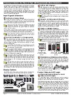
I/O Logic, Rear Panel or Breakout Box
The Tiger Operating System has many built-in logic func-
tions that can be used to develop sophisticated control
systems. The Tiger PMC has three logic inputs/outputs avail-
able via the LOCK, HOLD, and CAPTURE pins, and three logic
I/Os are available for input module use via pins D1, D2 and D3.
More complex I/O intensive applications require an opto-isolat-
ed I/O plug-in module, which supports six inputs and up
to 16 outputs. This module can connect to an external
Breakout Box that is DIN Rail mountable with screw ter-
minal blocks. There are also compatible DIN Rail mounting
electromechanical relays and SSR modules.
Retransmission 0-10V or 4-20mA
Tiger PMCs can have an optional single (0-10 V or 0/4-20
mA) or dual (0-10 V) analog output module installed. The
isolated 16-bit output is fully scalable and highly accurate.
With a compliance of up to 500
Ω
at 20mA, the 4-20 mA output
can be used over very long distances and still drive more than
one output device, such as a PID controlled valve positioner.
The analog outputs can be reversed to output 20mA to
4/0 or 10 to 0VDC. They can be scaled across any por-
tion of the digital range, up to full scale. The output can
be programmed to swing 0 to 20mA or 0 to 10V in one digital
count to drive external logic or SSRs as additional setpoints.
Under Macro Program Control, the analog outputs can be pro-
grammed to produce pulses or even sinewaves.
The easiest way to configure or program a Tiger PMC is with
the free user-friendly Configuration or Macro Development
Software. Serial I/O is provided via an optional Plug-in output
carrier board, which supports RS-232 or RS-485 output mod-
ules. If serial I/O is not required by the application, the serial
carrier board can be removed for reuse. The Tiger 320
Operating System supports several serial protocols, including
ASCII, Modbus RTU and Print Mode (which includes a printer
driver and support for direct meter to meter communications).
Also supported is DeviceNet, which requires a special dedi-
cated carrier board, and Ethernet (TCP/IP), which requires an
external converter box.
RS-232 or RS-485
Except for DeviceNet, all serial communication modes
supported by the Tiger can function with either RS-232 or
RS-485. The limitations of RS-232 are that only one meter at a
time can be connected to the serial port of a computer, and the
Serial Communication
DECISION
PLANN
ING
TIP
DECISION
DECISION
distance from the computer to the meter is limited in practical
terms to around 30 meters (100 feet).
Up to 32 meters can be connected on an RS-485 bus.
The differential current drive of the RS-485 bus ensures
signal integrity in the most harsh environments to dis-
tances up to 1230 meters (4000 feet). However, RS-485 gen-
erally requires a special RS-485 output card to be installed in
the computer or an external RS-232 to RS-485 converter has
to be used.
Select the Communication Mode Best
Suited to Your Application:
Modbus (RTU)
Modbus is widely used in industry. It has a
large base, and most SCADA and HMI soft-
ware packages support it. See also Modbus
Wrapped in Ethernet (Modbus/TCP) below.
There are 100s of HMI Touch Panel
Screens that are compatible with the
Tiger 320 Modbus interface.
ASCII
The meter configuration utility program and the development
software use the ASCII protocol. The ASCII protocol allows you
to write your own driver for your own application via the devel-
opment software and should provide the quickest development
time.
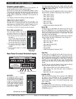
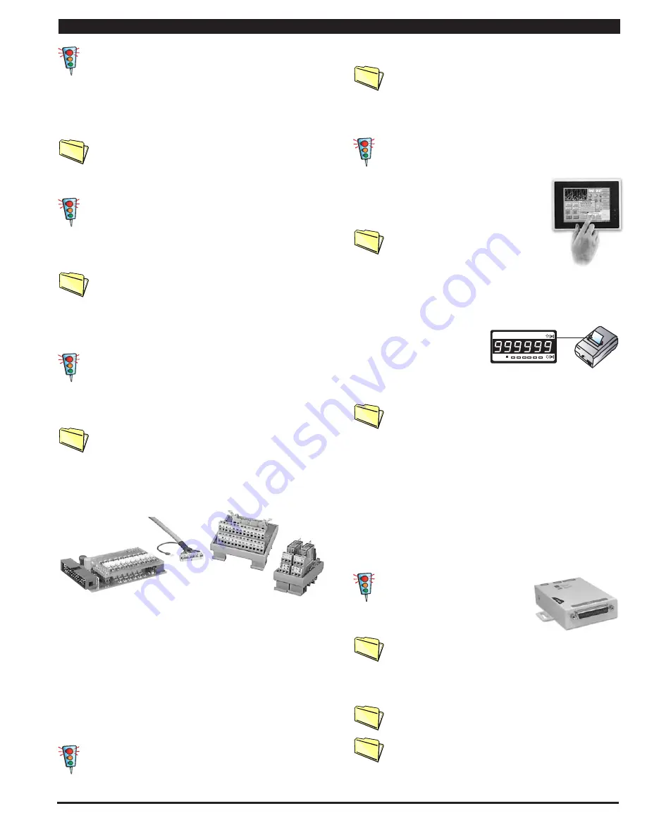
Print Mode
This is an ASCII based printer
driver output that enables the
serial port to be directly con-
nected to any serial printer with Epson compatibility. Printer
output can be configured to occur from a setpoint or on
demand, and can be date or time stamped.
The print mode can also be used for computer data log-
ging applications. The meter can be connected directly
to a computer, set up in Microsoft Hyperterminal mode,
with the meter programmed to output directly into a Microsoft
Excel spreadsheet format. (Also see Data Logging).
Print Mode for Meter to Meter Communication
Two or more Tiger PMCs can be connected together allowing
data to be transferred from the master meter (in print mode) to
the slave meter (in ASCII mode). This enables the meters to
share input data and control output functions.
Master Mode
This mode is for use with macro programming to expand the
meter to meter communication capability to multiples of Tiger
PMCs. This is useful for building an entire system of Tiger
PMCs, sharing information and control output resources.
Ethernet
Ethernet has become a popular
automation and control protocol. We
supply an ethernet output option and sever-
al external ethernet converters that are com-
patible with the serial outputs of Tiger PMCs.
Ethernet ASCII Wrap
- The ethernet output carrier
board option wraps the ASCII output into the Ethernet
protocol, and provides a T-base 10/100 Ethernet output
socket. This allows the Configuration Utility Program or the
Macro Development Software to run over a standard Ethernet
network. This enables the Tiger meter to be configured or
macro programmed from anywhere in the world via the web.
Up to 32 Tiger PMCs can be connected by RS-485 to a
single Ethernet Converter, which will support up to 32
separate IP addresses.
Ethernet Modbus Wrap
- This converter accepts the
Tiger PMC
’
s modbus protocol and outputs Modbus/TCP
through an Ethernet T-base 10 port. This has become a
standard for Ethernet on the factory floor. Many SCADA and
HMI software packages connect directly to Modbus/TCP.
DECISION
DECISION
DECISION
PLANN
ING
TIP
•
6 Inputs & 16 Outputs or 6 Inputs & 6 Outputs
•
Fully Programmable
Connects to DIN Rail
terminal block module
with 3M IDC cable
PLANN
ING
TIP
PLANN
ING
TIP
DIN Rail
Relay
Module
DIN Rail
Breakout Box
PLANN
ING
TIP
PLANN
ING
TIP
PLANN
ING
TIP
PLANN
ING
TIP
E
P
S
O
N
T
M
- U
2
1
0
* *
***
* * *
***
*
* *
***
* * *
***
*
*
*
*
*
2 4
: 0
7 : 0
0
J o
b . .
. . 1
4 3
2 2
J o
b . .
. . 1
4 3
2 2
P
r i n
t
P
r i n
t
P
r i n
t
Prog.
SP1
SP2
SP4
SP3
SP5
SP6
PLANN
ING
TIP


