


Texmate, Inc. Tel. (760) 598-9899
•
www.texmate.com
Page 16
6/23/04 DI-50B51 320 Series (NZ306)
The display showing 99999 represents the
OPERATIONAL DISPLAY
. After the meter
has been powered up, the display settles
and indicates the calibrated input signal.
This is known as the operational mode and
is generally referred to as the operational
display throughout the documentation.
P
are used throughout the range of Tiger 320 Series document
diagrams to represent the buttons and indicators on the meter, and
the actions involved in programming the meter:
Text or numbers shown between square brackets
in a description or procedure indicate the pro-
gramming code name of the function or the value
displayed on the meter display.
Symbol
Explanation
This symbol represents the
UP
button.
Shown in a diagram, pressing the UP button is
always indicated by a
right hand
.
This symbol represents the
DOWN
button.
Shown in a diagram, pressing the DOWN but-
ton is always indicated by a
right hand
.
Where two right hands are shown on the same
diagram with the word OR between them, this
indicates that both the
and
buttons can
be used to adjust the display: UP for increase,
DOWN for decrease.
This symbol represents the
PROGRAM
but-
ton. In a procedure, pressing the program but-
ton is always indicated by a
left hand
. A num-
ber indicates how many times it must be
pressed and released, or for how long it must
be pressed before releasing.
[Span]
[10000]
The exceptions to this rule are
when carrying out the
Model
and Software Code Version
Check
or the
Code Blanking
and Macro Check
.
When two displays are shown
together as black on grey, this
indicates that the display is tog-
gling (flashing) between the
name of the function and the
value or configuration setting.
Where a number is not defin-
able, the default setting [000] is
shown.
If an X appears in the descrip-
tion of a 3 digit programming
code or in a configuration pro-
cedure, this means that any
number displayed in that digit
is not relevant to the function
being explained, or more than
one choice can be made.
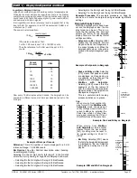
80
100
90
70
60
50
40
30
20
10
0
SP
SP
6
5
4
3
2
1
XX
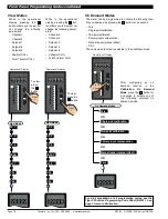
Programming procedures are graphic based with little descrip-
tive text.
Each procedure shows a number of meter panel displays running
in procedural steps from the top to the bottom of the page.
If need be, the procedure may run into two columns with the left
column running down the page and continuing at the top of the
right-hand column. Each action performed by the user is shown as
a numbered step.
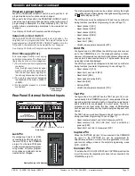
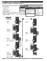
The meter uses a set of intuitive
software codes to allow maximum
user flexibility while maintaining an
easy programming process. To
configure the meter
’
s programming
codes, the meter uses the three
right-hand side display digits.
These are known as the 1st, 2nd,
and 3rd digits and can be seen in
the diagram opposite. To explain
software programming procedures,
diagrams are used to visually
describe the programming steps.
The following conventions
First
Digit
Second
Digit
Third
Digit
80
100
90
70
60
50
40
30
20
10
0
SP
SP
6
5
4
3
2
1
Operational Display
80
100
90
70
60
50
40
30
20
10
0
SP
SP
6
5
4
3
2
1
80
100
90
70
60
50
40
30
20
10
0
SP
SP
6
5
4
3
2
1
Step 1
Step 2
Operational Display
80
100
90
70
60
50
40
30
20
10
0
SP
SP
6
5
4
3
2
1
Press
at same
time
Press
at same
time
80
100
90
70
60
50
40
30
20
10
0
SP
SP
6
5
4
3
2
1
80
100
90
70
60
50
40
30
20
10
0
SP
SP
6
5
4
3
2
1
Press
at same
time
80
100
90
70
60
50
40
30
20
10
0
SP
SP
6
5
4
3
2
1
80
100
90
70
60
50
40
30
20
10
0
SP
SP
6
5
4
3
2
1
OR
All programming modes are entered from this level
.
Each procedural step shows
the meter display as it looks
before an action is per-
formed. The hand or hands
in the procedural step indi-
cate the action to be per-
formed and also how many
times, or for how long, the
button is to be pressed.
For example, the diagram
below shows the meter in the
operational display. With a
left hand pressing the
button and a right hand
pressing the
button, the
user is entering the
main pro-
gramming mode
. This is
indicated by the next dia-
gram displaying [bri] and [5].
This is the display brightness
mode and is the first sub-
menu of the main program-
ming mode.
P
Where a left and right hand are shown on separate buttons on
the same diagram, this indicates that the buttons must be
pressed at the same time.
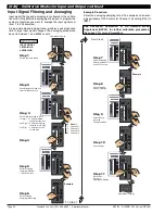
F
r
o
n
t
P
a
n
e
l
Pu
s
h
B
u
tt
o
n
C
o
nf
i
g
u
r
ati
o
n
a
nd
S
e
t
up f
o
r
P
r
og
r
a
mm
i
n
g
C
o
n
v
e
n
ti
o
n
s


