


Texmate, Inc. Tel. (760) 598-9899
•
www.texmate.com
Page 28
6/23/04 DI-50B51 320 Series (NZ306)
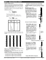
BARGRAPH DISPLAY SETTINGS
0 No Function
1 -
2 -
3 Set up Bar Scaling
BARGRAPH DISPLAY FORMAT
BARGRAPH TYPE
0 Linear
1 Via linearization Table 1
2
–
3 Log
–
10 Bar/Decade
4 Log
–
20 Bar/Decade
5 Log
–
25 Bar/Decade
6 Log
–
33 Bar/Decade
7 Log
–
50 Bar/Decade
CODE 10
–
BARGRAPH SETUP
0 Setpoints on Bar
1 Peak, Valley on Bar
2 -
3 -
4 Min/Max with setpoints (low end of bar =
VALLEY, high end of bar = PEAK)
5 -
6 -
7 Bar Only (no setpoints on the bar)
Note:
Data source for the bargraph is set
up in Code 1 [X51].
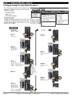
P
Set Up Scaling for Linear Bargraph
OR
P
P
Bar Low
Bar High
Bar Nominal
P
Set Up Scaling for Logarithmic Bargraph
OR
P
Reference
Bar Nominal
OR
OR
OR
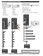
FIRST DIGIT
SECOND DIGIT
THIRD DIGIT
Display Format Mode
P
Program the three digits to the required
display function mode
LAST DIGIT ROUNDING
0 No rounding
1 Rounding by 2
’
s
2 Rounding by 5
’
s
3 Rounding by 10
’
s
DISPLAY UNITS
0 Decimal
1 24-hour clock mode
Hours: Minutes:
Seconds (6-digit ver-
sion only)
2 12-hour clock mode
(12:30 am is displayed
as 12:30A. 12:30 pm is
displayed as 12:30P)
3 24-hour clock mode
Days: Hours:Minutes
(6-digit version only)
4 -
5 -
6 -
7 Octal
DECIMAL POINT PLACEMENT
FIRST DIGIT
SECOND DIGIT
THIRD DIGIT
Note 2: These options are only for use with meters that have more than one display. With bar-
graph meters the PRIMARY display is the digital display, and the SECONDARY display is the
bargraph display.
Note 3: These functions are only available on selected input modules.
Note 4: If Code 1's display modes have been entered (second digit set to 5, 6, or 7), the dis-
play will cycle between Code 1 and the display functions mode each time the PROGRAM but-
ton is pressed. To leave the cycle, the Code 1 digits must be reset to any relevant function
between [X00] to [X20]. This takes you into Code 2.
FRONT PANEL ANNUNCIATORS
0 ON when Setpoints are ON (relay
energized)
1 ON when Setpoints are OFF (relay
de-energized)
2 Always OFF.
See Note 1
3 LED SP1 ON indicates RISING sig-
nal trend.
LED SP2 ON indicates FALLING
signal trend.
DISPLAY FUNCTIONS
0 Normal Display Mode (i.e. operational display
shows selected register) updates every 0.5
seconds
1 Manual Loader Mode (Direct Display).
See Note*
2 Update at sample rate selected in Code 2
3 -
4 -
5 Select data source as per 3rd digit.
See Note 4
6 Select display format as per 3rd digit.
See Note 4
7 Select text character as per 3rd digit.
See Note 4
SELECT DATA SOURCE FOR
0 Primary Display
1 Second Display.
See Note 2
2 Third Display.
See Note 2
3 Peak/Valley
4 Analog Output 1
5 Analog Output 2
6 Totalizer 1
7 Totalizer 2
CODE 1
–
DISPLAY CONFIGURATION
0 Result
1 Channel 1
2 Channel 2
3 Channel 3
4 Channel 4
5 Default Display
6 Total 1
7 Total 2
0 Result
1 Channel 1
2 Channel 2
3 Channel 3
4 Channel 4
5 Default Display
6 Total 1
7 Total 2
SELECT DISPLAY FORMAT FOR
SELECT TEXT CHARACTER FOR
FIRST DIGIT
SECOND DIGIT
THIRD DIGIT
See diagram below
See diagram below
See diagram below
Select Data Source
Select Display Format
Select Last Digit Text Character
Note*: For the Manual Loader Mode (Direct Display) to work, with Code 1 set to [X54] the data source
for the analog output (1 or 2) must be set to [diSP].
Operating range upper and lower limits can be set for the manual loader mode.
The setpoint activation values for setpoint 5 becomes the upper limit and setpoint 6 becomes the lower
limit.
When either the direct display or on demand manual loader mode is programmed into the meter, the
values for setpoint 5 and setpoint 6 are activated as upper and lower limits.
See Analog Output Supplement for further details.
0 No decimal point
1 - XX.XX.XX
2 - X.XXXXX
3
X.XXXX
4
X.XXX
5
X.XX
6
X.X
7 Decimal Point set from the
rear (X.XXXX to XXXXX)
See Note 3.
Also See Note 4.
Note:
Selecting 1, 2, or
3 in the 2nd digit
of this mode con-
figures the display
of the selected
channel
as
a
clock.
I
n
i
ti
al
S
e
t
up P
r
o
c
e
du
r
e
s
[
C
o
d
E
_
1
]
-
D
i
s
p
l
a
y
C
o
nf
i
g
u
r
ati
o
n
c
o
n
ti
nu
e
d
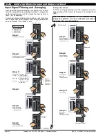
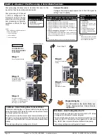
Use the
buttons to cycle through
the Registers Menu and Registers (1 to
244) to select data source for displays,
peak and valley, totalizers and analog out-
put (also see page 48).
Select Data Source
Use the
button
to cycle through
the menu, and the
button to cycle
back.
Select Last Digit Text Character
P
[rESLt]
[Ch1]
[Ch2]
[Ch3]
[Ch4]
[tot_1]
[tot_2]
[PEAK]
[tArE]
[VALEY]
[diSP]
[ 1]
[ 10]
[100]
[200]
[244]
Note 1: LED annunciators are always off, except when the meter is in single channel VOLTAGE or CURRENT mode and Code 3 = [X6X], or Code 7 = [X6X] in which case the LEDs indicate which 32-point table
has been selected from the rear pins (SP1 = Table 1, SP2 = Table 2, SP3 = Table 3, SP4 = Table 4).


