


Page 45
6/23/04 DI-50B51 320 Series (NZ306)
Texmate, Inc. Tel. (760) 598-9899
•
www.texmate.com
From Step 5
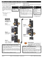
Step 4
Step 5
Step 3
Step 1
Operational Display
80
100
90
70
60
50
40
30
20
10
0
SP
SP
6
5
4
3
2
1
Press
at same
time
Press
at same
time
Enter
Brightness Mode
0
80
100
90
70
60
50
40
30
20
10
0
SP
SP
6
5
4
3
2
1
80
100
90
70
60
50
40
30
20
10
0
SP
SP
6
5
4
3
2
1
80
100
90
70
60
50
40
30
20
10
0
SP
SP
6
5
4
3
2
1
Press
1
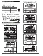
Step 6
Step 7
Step 8
Step 9
Step 10
Exit SPC_2.
Return to
Operational Display
Operational Display
80
100
90
70
60
50
40
30
20
10
0
SP
SP
6
5
4
3
2
1
80
100
90
70
60
50
40
30
20
10
0
SP
SP
6
5
4
3
2
1
80
100
90
70
60
50
40
30
20
10
0
SP
SP
6
5
4
3
2
1
Press
1
80
100
90
70
60
50
40
30
20
10
0
SP
SP
6
5
4
3
2
1
Press
1
Press
at same
time
Press
at same
time
80
100
90
70
60
50
40
30
20
10
0
SP
SP
6
5
4
3
2
1
80
100
90
70
60
50
40
30
20
10
0
SP
SP
6
5
4
3
2
1
80
100
90
70
60
50
40
30
20
10
0
SP
SP
6
5
4
3
2
1
80
100
90
70
60
50
40
30
20
10
0
SP
SP
6
5
4
3
2
1
Example
Example
Example
80
100
90
70
60
50
40
30
20
10
0
SP
SP
6
5
4
3
2
1
Press
1
To Step 6
Reset 2nd digit to 0. If the 2nd
digit is not reset to 0, the
meter will constantly cycle
thru SPC_1
Save SP1
control settings
Save SP1 activation
value setting
Select [CH1] as the SP1
activation source. See
diagram on Pages 36
and 37
Enter SP1
source sub-menu
Save SP1
control settings
Set SPC_1 to [013]:
1st Digit = 0 Energize above SP1 value
or 1 to energize below SP1 value
2nd Digit = 1 Select source for SP1
3rd Digit = 3 Relay latching with manual reset
CONFIGURE LEVEL 1
SETPOINT & RELAY
FUNCTIONS
Step 2
80
100
90
70
60
50
40
30
20
10
0
SP
SP
6
5
4
3
2
1
80
100
90
70
60
50
40
30
20
10
0
SP
SP
6
5
4
3
2
1
Adjust setpoint 1 (SP1)
activation value to e.g.
500 counts
OR
OR
OR
OR
Setpoint Programming Mode
–
Programming Procedures
Example Procedure:
The following procedure describes how to program setpoint 1
(SP1) for the following
Level 1
setpoint and relay functions:
•
SP1 to activate from Channel 1 (CH1).
•
Relay to energize above or below SP1 value.
•
Relay to latch with manual relay reset.
Programming tip
All required setpoint activation values (SP1 to SP6) can be adjusted before
programming setpoint and relay control function settings. See
Setpoint
Programming Mode Logic Diagram
on Page 46.
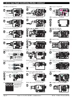
ST
ST
AR
AR
T HERE
T HERE
S
e
t
p
oi
n
t
P
r
og
r
a
mm
i
n
g
M
o
d
e
c
o
n
ti
nu
e
d
See
Setpoints and Relays Supplement (NZ201)
for proce-
dures to program all setpoint and relay operational levels
(Level 1 to Level 3).
(See page 3 for more information).


