


Texmate, Inc. Tel. (760) 598-9899 • www.texmate.com
Page 2
6/23/04 DI-50B51 320 Series (NZ306)
Inputs
Inputs Available:
More than 120 single, dual, triple and quad input
signal conditioners available covering all types of analog, digital and
mixed input signals (see page 53).
Accuracy:
Tiger 320 PMCs enable the user to establish any
degree of system accuracy required. Built-in compensation and lin-
earization functions enable system accuracies of the order of
±0.0001% of reading for analog inputs. Stop -Start time resolution
from ±1sec to ±0.7nsec. Digital input and pulse counts ±1 count.
A/D Convertors:
A Dual Slope, bipolar 17 bit A/D is provided as
standard on the main board. SMART modules can have 24 bit or 16
bit Delta-Sigma A/D convertors that utilize the internal I2C BUS.
Temperature Coefficient:
Typically 30ppm/˚C. Compensation can
be utilized to achieve system temperature coefficients of 1ppm.
Warm Up Time:
Up to 10 minutes, depending on input module.
Conversion Rate:
Typically 10 samples per second. However,
SMART input modules are available that can convert at 60, 240, 480
or 960 samples per second.
Control Output Rate:
Can be selected for 100msec or 10msec.
Some SMART modules have SSR outputs that react within 1.2msec.
Excitation Voltage:
Depends on input module selected. Typically,
5V, 10V or 24VDC is provided.
Outputs
(See pages 50-51 for pinouts and details of modular construction)
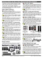
Three Optional Plug-in Carrier Boards:
Provide four different serial
outputs or no serial output, support single or dual analog outputs,
and accept any one of seven different plug-in I/O modules.
1. Standard Carrier Board:
Is available without a serial output, or
with either an isolated RS-232 or an isolated RS-485 (RJ-6 socket).
2. DeviceNet Carrier Board:
5 pin 3.5mm screw terminal.
3. Ethernet Carrier Board:
10/100Base-T Ethernet (RJ-45 socket).
Two Isolated Analog Output Options:
Mounted on any carrier board.
1. Single Analog Output:
Fully scalable from 4 to 20mA or 0 to 20mA
(or reverse) and selectable for 0 to 10VDC (or reverse).
2. Dual Analog Output:
Fully scalable from 0 to 10VDC (or reverse).
Analog Output Specifications:
Accuracy: 0.02% FS.
Resolution: 16-bit Delta-Sigma D/A provides 0.4µA on current
scaling, 250µV on voltage scaling. Compliance: 500
Ω
maximum
for current output. 500
Ω
minimum for voltage output. Update
Rate: Typical 7 per second. Step Response: Typical 6msec to a
display change. Scalable: From 1 count to full scale.
Seven I/O Modules:
Plug into any carrier board from rear.
1. Four Relay Module:
Available in six combinations from one relay up
to a total of two 10A Form C Relays* and two 5A Form A Relays**.
2. Four Relay Module:
Available with one to four 5A Form A Relays**.
3. Six Relay Module:
Available with five or six 5A Form A Relays**.
*Form C Relay Specifications:
10A 240VAC~1/2 HP, 8A
24VDC. Isolation 3000V. UL and CSA listed.
**Form A Relay Specifications:
5A 240VAC, 4A 24VDC.
Isolation 3000V. UL and CSA listed.
4. Four Solid State Relay (SSR) Module:
Available with one to four
independent (210mA DC only) or (140mA AC/DC) SSRs (400V max).
5. Six Output 5VDC / TTL or Open Collector:
Available with 0 to 5V
or 0 to V+ (40VDC max).
6. Opto Isolated I/O Module:
Available in either 6 Outputs & 6 Inputs, or
16 Outputs and 6 Inputs. For connection to an external breakout box.
7. Flash Card Memory Module:
Available with 8 or 16 MB memory.
Power Supplies
Auto sensing AC/DC (DC to 400Hz) hi volts std, low volts optional.
PS1 (standard):
85-265VAC / 95-370VDC @ 4W max 5W.
PS2 (optional):
14-48VAC / 10-72 VDC @ 4W max 5W.
Environmental
(See Rear page for IP-65 & NEMA-4 options)
Operating Temperature:
0 to 50 ˚C (32 ˚F to 122 ˚F).
Storage Temperature:
-20 ˚C to 70 ˚C (-4 ˚F to 158 ˚F).
Relative Humidity:
95% (non-condensing) at 40 ˚C (104 ˚F).
Mechanical
(See Rear page for more details)
Case Dimensions:
1/8 DIN, 96x48mm (3.78” x 1.89”)
Case Material:
94V-0 UL rated self-extinguishing polycarbonate.
Weight:
11.5 oz (0.79 lbs), 14 oz (0.96 lbs) when packed.
Approvals
CE:
As per EN-61000-3/4/6 and EN-61010-1.
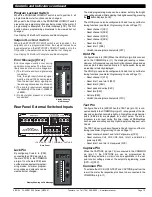
Display
Digital Display:
7-segment, 0.31” (8 mm) LEDs.
Display Color:
Red (std). Green (optional).
Digital Display Range:
-19999 to 99999
Update Rate:
3 to 10 times per second
Bargraph Display:
51-segment bargraph.
Bargraph Color:
Red (std). Green (optional).
Display Dimming:
8 brightness levels. Front Panel selectable
Scrolling Display Text Messaging:
Full alphanumeric, 7-segment
text characters supported on T Version with macros.
Polarity:
Assumed positive. Displays - negative
Decimal Point:
Front panel, user selectable to five positions.
Overrange Indication:
Underrange Indication:
Front Panel Controls:
PROGRAM, UP and DOWN.
Operating System
(Tiger 320)
Processor:
32 bit with floating point maths (18.4 MHz).
Flash Memory:
64k, 4k for use by custom macros.
RAM:
1.25k and FeRAM 4k.
EEPROM:
E Version 4k standard, T Version 32k standard. Memory
upgrades available to 32k for LIN Tables and 1MB for Data Logging
and custom macros.
Registers:
6144 registers comprised of 8, 16 or 32 bit signed,
unsigned or floating point registers, implemented in a combination
of RAM, FeRAM, Flash and EEPROM.
Internal communication BUS:
32 bit I2C BUS
Real Time Clock (option):
Year:Month:Date:Hour:Minute:Second
with 15 yr Lithium battery backup.
Configuration:
Supports Front Panel Programming Codes and a
PC-based Configuration Utility Program, which may be downloaded
free from the web. T Version also supports custom macros.
Development System for Custom Macros
The Tiger 320 Macro Development System, which may be down-
loaded free from the web, can be used to create powerful macro
software that allows Tiger 320 T Versions to be easily customized to
suit any proprietary OEM application (see page 11).
Installed Application Software Includes
Counter Functions:
Two built-in counters. UP counters, DOWN
counters, UP/DOWN counters and high speed quadrature counters.
Data Logging:
Logging with a date/time stamp, initiated at timed
intervals, by activation of a setpoint, or manually. Data stored in
internal 1MB EEPROM or in a removable 4 to 128M Flash Card
Memory Module. Endless loop recording is supported.
Input Compensation:
Provides compensation to the primary input
channel (CH1) via channels 2, 3 or 4.
Linearization:
4 selectable 32 point or one 125 point flexible lin-
earization tables are provided.
Logic I/O:
28 Macro programmable I/O ports supported.
Manual Loader:
Front panel adjustable, 4 to 20mA or 0 to 10V iso-
lated analog output.
Math Functions:
Cross channel math functions to calculate the
sum, difference, ratio or the product of two inputs.
On Demand Functions:
Tare, compensation and calibration.
Peak and Valley:
The meter can retain peak and valley (min/max)
information and recall this on the front panel.
Remote Setpoint Input:
Remote setpoint input via channel 2.
Serial Output Protocols:
Selectable communication modes
include ASCII, Modbus (RTU), Master Mode (for meter to meter
communication) and an Epson compatible printer driver. DeviceNet
and Ethernet optional output carrier boards are also supported.
Setpoint Functions:
Six super smart setpoints with fully config-
urable hysteresis, on and off delays, one shot, pulse and repeat
timers, latching, dual PID, setpoint tracking, resetting of registers,
initiating of logging and printing.
Signal Conditioning Functions:
Averaging, smart filter, rounding,
square root,auto zero maintenance.
Timer:
Timer functions supported in either time-up, time-down, or
real-time clock modes.
Totalizer:
Two totalizers for running total and batch totals of a
process signal that can be accumulated over time.
S
p
e
c
i
f
i
c
ati
o
n
s


