


Texmate, Inc. Tel. (760) 598-9899
•
www.texmate.com
Page 46
6/23/04 DI-50B51 320 Series (NZ306)
P
X
X
P
P
P
to
P
P
P
P
P
P
P
P
X
X
X
X
Set Up Hysteresis, Deviation & PID Mode Settings
Set Deviation from 1 to 65535
counts. Selected counts apply +
and
–
from setpoint value
Set the Span
Set the Proportional Band Value
Set the Integral Value
Set the Derivative Value
Set the Anti-reset Wind-up % PB
Set the Minimum Cycle Time
PID FROM SETPOINT
1 AND 2 ONLY
MIN 0%
MAX 999.9%
MIN 0
MAX 99999
MIN 0
MAX 9999.9
MIN 0
MAX 999.9
MIN 0.1%
MAX 100.0%
MIN 0 secs
MAX 1000.0 secs
Note:
The output from RELAY
1 is disabled if minimum
cycle time set to 0
0 No Latching
1 Relay Latched
2 Manual Relay Reset
3 Relay Latched with Manual Relay
Reset
4 Relay Latched Off
5 Hysteresis, Deviation & PID Mode
(includes SP Tracking)
6 Timer Modes:
•
Normal Delay.
•
Repeat ON.
•
Pulse ON.
•
1-Shot ON.
•
Repeat OFF.
•
Pulse OFF.
•
1-Shot OFF.
Note:
In PID mode, all functions on SP1
set in [XX6] are not functional.
7 Advanced Functions Mode:
•
Reset Trigger.
•
Reset Destination.
•
Reset Mode.
•
Reset Constant.
•
Trigger Print from SP.
•
Trigger Log from SP.
•
Annunciator Flashing & SP Tracking.
Note:
[XX5], [XX6], and [XX7] are set up
procedure settings only. To finish,
reset to 0-4 as required for setpoint
latching and relay reset modes.
Relay Energize Function
0 Energized ABOVE setpoint value.
1 Energized BELOW setpoint value.
2 Energized ABOVE setpoint value with FALLING
INPUT SIGNAL INITIAL START-UP INHIBIT.
3 Energized BELOW setpoint value with RISING
INPUT SIGNAL INITIAL START-UP INHIBIT.
SP Activation Source
0 Activate
Setpoint
Source
from
Selected Register
1 Select Source for Setpoint from Selected
Register
Note:
[X1X] is a register selection procedure
only. To finish, reset to [X0X] to activate
the selection, or reset to 2-7 as required
for digital input selection.
2 Digital Input
–
Capture Pin
3 Digital Input
–
D1
4 Digital Input
–
D2
5 Digital Input
–
D3
6 HOLD Pin
7 LOCK Pin
SP Delay & Timing Functions
FIRST DIGIT
SECOND DIGIT
THIRD DIGIT
See Set Up
H y s t e r e s i s ,
Deviation & PID
Mode Settings
below
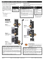
Go to Page 47
The diagram below and continued on Page 47 shows the 1st, 2nd, and 3rd digit control settings for the setpoints and relays.
Setpoint & Relay Control Settings Diagram
Go to Page 47
Select Tracking Setting
Select Flash Setting OFF or ON
OFF= Tracking Off
1
= SPX tracks SP1
2
= SPX tracks SP2
3
= SPX tracks SP3
4
= SPX tracks SP4
5
= SPX tracks SP5
6
= SPX tracks SP6
Set Hysteresis from 0 to 65535
counts. Selected counts apply +
and
–
from setpoint value
Third digit
set to [XX5]
Reset SPC_X to [XX0]
Programming Tip
If you do not require any
of the functions in this
mode, ensure it is set to:
Note:
If PID is selected in [XX5],
the Timer Delay [XX6] and
Reset and Trigger Functions
[XX7] revert to [ModE][oFF]
and cannot be adjusted.
S
e
t
p
oi
n
t
P
r
og
r
a
mm
i
n
g
M
o
d
e
c
o
n
ti
nu
e
d
Use the
buttons to
cycle through the Registers
Menu and Registers (1 to 244)
to select data source for set-
points (also see page 48).
Select Source for Setpoint Functions
P
[rESLt]
[Ch1]
[Ch2]
[Ch3]
[Ch4]
[tot_1]
[tot_2]
[PEAK]
[tArE]
[VALEY]
[diSP]
[ 1]
[ 10]
[100]
[200]
[244]


