Texmate DI-50EB51 Скачать руководство пользователя страница 27

Page 27

6/23/04   DI-50B51 320 Series (NZ306)

Texmate, Inc. Tel. (760) 598-9899  

  www.texmate.com

Logarithmic Bargraph Scaling

Logarithmic scales are used in a wide variety of measurements.
Probably the most well known logarithmic scale is the Richter
scale for measuring earthquakes. Other log scales used include
sound level (dB), radio frequency signals, power levels (dBm),
and numerous radiation signals.
In all logarithmic scales a reference level is required that is the
level at 0 dB. For example, in an RF measurement 0 dBm is at
a reference of 1 mW.
The scale is calculated from:

If the meter is scaled so that:
1 mW = 100 counts and 1 W = 100,000 counts
Then the reference for 0 dBm would be set to 100 
counts:

10 log

10

counts (input)

reference

10 log

10

(input)

100

= 0 dBm

Decade

(Counts)

20

10

0

10

20

30

40

1

10

100

1000

10,000

100,000

1,000,000

Now every 10 dBm represents a decade, the bargraph can be
scaled to a different amount of bars per decade (as set in the
3rd digit).

dBm

I

n

i

ti

al


S

e

t

up P

r

o

c

e

du

r

e

s

[

C

o

d

E

_

1

]


-


D

i

s

p

l

a

y


C

o

nf

i

g

u

r

ati

o

c

o

n

ti

nu

e

d

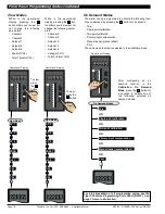
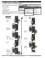
Bargraph Display Format

After  the  bargraph  colors  have  been
set and the bargraph scaled, the dis-
play  format  can  be  set. This  is  nor-
mally  the  final  setting. The  2nd  digit
selects  the  format  of  the  bargraph
display. There are four display format
settings available:

Setpoints  on  Bar

. Selecting  [X0X]

means  that  the  setpoints  are  dis-
played on the bar as lit segments in
the  current  display  color. When  the
bargraph  lights  up  on  or  beyond  a
setpoint, the setpoint segment goes
out.

100

80

60

40

20

0

SP4

SP5

SP6

SP3

SP2

SP1

SP

Segments

Go Out

Lit SP

Segments

Lit Segments

Showing

Signal 

Example of Setpoints on Bargraph

Reference

. This is the number of counts displayed for a 0 dB

reference. Range: 1 to 99999 counts.

Bar  Nominal

. See  Bar  Nominal  description  under  heading:

Linear Bargraph Scaling.
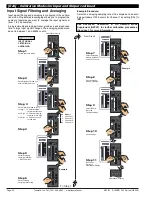
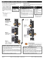
Selecting 

3

in the 1st digit and 

3, 4, 5, 6, or 7 

in the 3rd digit

enters the Set Up Scaling for Logarithmic Bargraph sub-menu:

Selecting 

3

in the 3rd digit sets the log to 10 Bar/Decade.

Selecting 

4

in the 3rd digit sets the log to 20 Bar/Decade.

Selecting 

5

in the 3rd digit sets the log to 25 Bar/Decade.

100 dBm

80 dBm

60 dBm

40 dBm

20 dBm

0 dBm

10 Bars/Decade

90 dBm

70 dBm

50 dBm

30 dBm

10 dBm

40 dBm

20 dBm

0 dBm

20 Bars/Decade

50 dBm

30 dBm

10 dBm

40 dBm

0 dBm

25 Bars/Decade

30 dBm

20 dBm

10 dBm

0 dBm

33 Bars/Decade

30 dBm

20 dBm

10 dBm

0 dBm

50 Bars/Decade

20 dBm

10 dBm

100

1000

10,000

100,000

1,000,000

100

1000

10,000

100,000

1,000,000

100

1000

10,000

100,000

1,000,000

100

1000

10,000

100,000

100

1000

10,000

Example of Bars per Decade
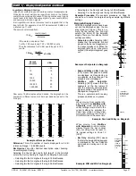
Peak and Valley on Bar

. Selecting

[X1X]  means  that  peak  and  valley
are  displayed  as  lit  segments  and
are  updated  as  they  change. The
setpoints are not displayed.

Min/Max 

with 

Setpoints

.

Selecting  [X4X]  means  that  the
segments  of  the  bar  remain  lit
over  the  minimum  and  maximum
signal variations. The setpoints are
displayed as lit segments.
This  is  a  useful  mode  for  seeing
process variations at a glance.

Note:

When  moving  from  another  dis-
play format to the Min/Max with
Setpoints 
mode,  the  peak  and
valley settings must be set to the
current  settings  by  entering  the
Peak  View  mode  or  Valley  View
mode  and  pressing  the  UP  and
DOWN buttons at the same time.

PEAK

Input Signal
Displayed using
Bargraph Center
Zero Mode

VALLEY

Example: Peak and Valley on Bargraph

MAX

All segments
between MAX
and MIN
remain lit
except any
SPs in that
area 

SP4

SP5

SP6

SP3

SP2

SP1

MIN

Example: MIN and MAX on Bargraph

When  moving  from  Min/Max
with Setpoints 
mode to another
display  format,  the  bar  nominal
[bAr_n]  setting  must  be  reset  to
its  original  settings  in  Code  10
[3XX].

Bar  Only

. Selecting  [X7X]  means

that only the bargraph display signal
is  displayed  on  the  bar. Setpoints
and  peak  and  valley  are  not  dis-
played.

Selecting 

6

in the 3rd digit sets the log to 33 Bar/Decade.

Selecting 

7

in the 3rd digit sets the log to 50 Bar/Decade.

Example  Procedure

. The  example  procedure  on  Page  34

shows  how  to  scale  the  bargraph  using  example  logarithmic
settings.

Содержание DI-50EB51

Страница 1: ...low voltage AC DC power supply A powerful intelligent 5 digit 51 segment Programmable Meter Controller PMC with modular outputs input signal conditioning and advanced software features for monitoring...

Страница 2: ...58 F Relative Humidity 95 non condensing at 40 C 104 F Mechanical See Rear page for more details Case Dimensions 1 8 DIN 96x48mm 3 78 x 1 89 Case Material 94V 0 UL rated self extinguishing polycarbona...

Страница 3: ...lable on request or can be viewed and downloaded from the document server on our website Tiger 320 Series Modular Literature Overview The model specific data sheet user manual contains Technical Speci...

Страница 4: ...ing from a PC A Plug in I O Module is available with removable Flash Card Memory for high capacity or long term data logging Flash Cards are available from 4 to 128 Meg Up to 1MB of non volatile on bo...

Страница 5: ...120 Different Input Signal Conditioning Modules Latched OFF Reset Reset Latched ON Choose from over 120 different single dual triple and quad input signal conditioners Mixed function and smart module...

Страница 6: ...omized to suit any OEM application and be quickly produced in large or small quantities for push but tons or membrane touch pads Control Outputs I O Logic Electromechanical Relays or Solid State Contr...

Страница 7: ...ECISION distance from the computer to the meter is limited in practical terms to around 30 meters 100 feet Up to 32 meters can be connected on an RS 485 bus The differential current drive of the RS 48...

Страница 8: ...use them and do not require any knowledge of BASIC programming Development Software Planning to Use the Tiger 320 Series of Programmable Meter Controllers continued Planning to Harness the Power of Ti...

Страница 9: ...source for OUTPUT PROCESSING Select data source for Setpoint 1 2 3 4 5 6 Analog output 1 2 Data logging Select data source for DISPLAY PROCESSING Select data source for Display 1 Default Display Chan...

Страница 10: ...sult Channel 1 Channel 2 Channel 3 Channel 4 Totalisator 1 Totalisator 2 Peak Valley Tare Setpoint 1 Setpoint 2 Setpoint 3 Setpoint 4 Setpoint 5 Setpoint 6 PID 1 PID 2 Register Reset Value Constant In...

Страница 11: ...ry product There is also a growing library of off the shelf application spe cific macro programs available Many only need the blanks to be filled in to use them and this does not require any knowledge...

Страница 12: ...and Sampling Rate 35 Code 3 Channel 1 Post Processing and Serial Mode Functions 36 Code 4 Channel 2 Measurement Task and Sampling Rate 37 Code 5 Channel 3 Functions 38 Code 6 Channel 4 Functions 39 Co...

Страница 13: ...ttings 22 40 Literature Overview Model Specific Data Sheets User Manuals 3 Other Tiger 320 Series Related Software 3 Programming Code Sheet 3 Supplements to Data Sheets User Manuals 3 Macros 4 8 11 Ma...

Страница 14: ...and 6 valley and total 2 Once into the viewing routine pressing the button moves through each displayed parameter See Display with Faceplate and Bezel diagram Annunciator LEDs The annunciator LEDs can...

Страница 15: ...r up 1XX Reset counters CH1 CH2 CH3 CH4 total 1 and total 2 at power up 2XX Reset total 1 and total 2 at power up 3XX Capture Pin When the CAPTURE pin pin 12 is connected to the COMMON pin pin 11 the...

Страница 16: ...3 2 1 XX Programming procedures are graphic based with little descrip tive text Each procedure shows a number of meter panel displays running in procedural steps from the top to the bottom of the pag...

Страница 17: ...Setpoint 3 SP_3 Setpoint 4 SP_4 Setpoint 5 SP_5 Setpoint 6 SP_6 Enter these menus to adjust SP activation values Setpoint Relay Control Settings Mode P P P P P Setpoint 1 SPC_1 Setpoint 2 SPC_2 Setpo...

Страница 18: ...bration Primary input compensation Manual loader manual offset Print View Mode Ch3 SP_1 SP_3 SP_5 PEAK tot_1 Ch1 Operational Display 80 100 90 70 60 50 40 30 20 10 0 SP SP 6 5 4 3 2 1 Press 1 View Mod...

Страница 19: ...nking turned ON all main and setpoint codes that have been blanked out during factory programming are hidden preventing them from being reprogrammed Any codes that have not been blanked out are still...

Страница 20: ...6 5 4 3 2 1 Press 1 Example Code Blanking Step 4 Press the button to switch code blanking OFF NOTE Unless otherwise requested the factory default setting is oFF Display Configuration Once you have re...

Страница 21: ...RTD requires RTD 385 input source 4 Calibrate Smart Input Module Note This function is not available on all input modules 5 Calibrate Analog Output requires multimeter con nected to pins 16 and 17 6 7...

Страница 22: ...veraging win dow can be set to between 1 and 65535 counts See the calibration modes diagram on Page 21 showing a breakdown of 1st 2nd and 3rd digits See Input Signal Sampling Showing Averaging Window...

Страница 23: ...0 SP SP 6 5 4 3 2 1 80 100 90 70 60 50 40 30 20 10 0 SP SP 6 5 4 3 2 1 To Step 7 Pass Brightness Mode and enter Calibration Mode Select the No Function Calibration Mode 000 Save Calibration Mode 000 s...

Страница 24: ...0 SP SP 6 5 4 3 2 1 80 100 90 70 60 50 40 30 20 10 0 SP SP 6 5 4 3 2 1 Press 1 80 100 90 70 60 50 40 30 20 10 0 SP SP 6 5 4 3 2 1 Press 1 Press at same time Press at same time 80 100 90 70 60 50 40 30...

Страница 25: ...5X enters the Data Source sub menu Selecting X6X enters the Display Format sub menu Selecting X7X enters the Last DigitText Character sub menu Data Source 2nd Digit X5X The digital display is the prim...

Страница 26: ...one of 54 char acters and apply it to the last digit when the meter is in the oper ational display For example if the meter was measuring a temperature the display could be configured to display the...

Страница 27: ...Scaling for Logarithmic Bargraph sub menu Selecting 3 in the 3rd digit sets the log to 10 Bar Decade Selecting 4 in the 3rd digit sets the log to 20 Bar Decade Selecting 5 in the 3rd digit sets the l...

Страница 28: ...ader Mode Direct Display See Note 2 Update at sample rate selected in Code 2 3 4 5 Select data source as per 3rd digit See Note 4 6 Select display format as per 3rd digit See Note 4 7 Select text char...

Страница 29: ...40 30 20 10 0 SP SP 6 5 4 3 2 1 Press 1 80 100 90 70 60 50 40 30 20 10 0 SP SP 6 5 4 3 2 1 Press 1 Press at same time Press at same time X X OR OR OR Programming Tip Pressing the and buttons at the s...

Страница 30: ...3 2 1 80 100 90 70 60 50 40 30 20 10 0 SP SP 6 5 4 3 2 1 80 100 90 70 60 50 40 30 20 10 0 SP SP 6 5 4 3 2 1 Press 2 80 100 90 70 60 50 40 30 20 10 0 SP SP 6 5 4 3 2 1 80 100 90 70 60 50 40 30 20 10 0...

Страница 31: ...Brightness and Calibration Modes and enter Code 1 Press 1 X Set Code to X71 1st Digit X Note relevant 2nd Digit 7 Selects text character mode 3rd Digit 1 Selects channel 1 Select Text Character C fro...

Страница 32: ...6 5 4 3 2 1 80 100 90 70 60 50 40 30 20 10 0 SP SP 6 5 4 3 2 1 Press 2 80 100 90 70 60 50 40 30 20 10 0 SP SP 6 5 4 3 2 1 80 100 90 70 60 50 40 30 20 10 0 SP SP 6 5 4 3 2 1 80 100 90 70 60 50 40 30 2...

Страница 33: ...Operational Display Pass Brightness and Calibration Modes and enter Code 10 Step 6 Example Example Example From Step 6 To Step 7 Step 8 Step 7 Step 10 Step 9 80 100 90 70 60 50 40 30 20 10 0 SP SP 6...

Страница 34: ...P SP 6 5 4 3 2 1 80 100 90 70 60 50 40 30 20 10 0 SP SP 6 5 4 3 2 1 Press 1 OR Operational Display Example 80 100 90 70 60 50 40 30 20 10 0 SP SP 6 5 4 3 2 1 80 100 90 70 60 50 40 30 20 10 0 SP SP 6 5...

Страница 35: ...0 Hz 6 99 kHz range from 1 Hz 1 s gate 7 655 35 kHz range from 10 Hz 0 1 s gate PERIOD MEASUREMENT 0 99 999 s 1 9 9999 s 2 999 99 ms 3 99 999 ms COUNTER RESIDENT TIMER CLOCK 0 Counter input with 16 b...

Страница 36: ...elected from the rear pins of selected input modules The selected table is not available if CH2 CH3 or CH4 is oper ating in the analog output mode CH1 must be set to Voltage Current in Code 2 X0X See...

Страница 37: ...is processed and displayed on CH2 Measurement task and 32 point linearization for CH2 is config ured in the 1st and 2nd digits of Code 4 The diagram opposite lists the available configuration selectio...

Страница 38: ...for Channel 3 When a triple input signal conditioner is installed the third input signal is processed and displayed on CH3 Post processing and measure ment task functions for CH3 are configured in the...

Страница 39: ...pe R 3 Type S 4 Type T 5 Type B 6 Type N 7 Select user defined linearization table Table 1 set up in CAL 24X FOR RTD TYPE 2 3 4 WIRE 0 Resistance 1 RTD 385 2 RTD 392 3 RTD 120 4 Cn 10 MEASUREMENT TASK...

Страница 40: ...2 32 point Linearization on Result using Table 2 See Note 5 3 32 point Linearization on Result using Table 3 See Note 5 4 32 point Linearization on Result using Table 4 See Note 5 5 125 point Lineari...

Страница 41: ...Time stamp format 3 Hrs Min Sec ALL ABOVE ARE REAL TIME CLOCK OPTIONS LOG OR PRINT TRIGGER 0 No trigger 1 Trigger on Demand from PRO GRAM Button 2 Trigger on Demand from F1 Button 3 Trigger on Demand...

Страница 42: ...de a selection of 20 relay configuration options for DI 50 meters Three electromechanical relay output modules support a combination of 5 A Form A and 10 A Form C relays providing 12 configuration opt...

Страница 43: ...can be programmed in relay latching modes Setpoint Reset Trigger Setpoints can be programmed to reset selected registers or be manually reset They can also trigger a data print or a data log DUAL PID...

Страница 44: ...F Modes These are delay modes were the relay is normally on and pulses off when the setpoint activates 1 Shot OFF mode Programmable Minimum OFF time SP OFF SP ON Adj MIN OFF T RLY ON RLY OFF Adj DOB S...

Страница 45: ...eter will constantly cycle thru SPC_1 Save SP1 control settings Save SP1 activation value setting Select CH1 as the SP1 activation source See diagram on Pages 36 and 37 Enter SP1 source sub menu Save...

Страница 46: ...T UP INHIBIT 3 Energized BELOW setpoint value with RISING INPUT SIGNAL INITIAL START UP INHIBIT SP Activation Source 0 Activate Setpoint Source from Selected Register 1 Select Source for Setpoint from...

Страница 47: ...lse OFF Mode Single Actuation Repeat OFF Mode Multiple Actuation DOM 0 1 0 001 to 6553 5 65 535 secs Setpoint Programming Mode continued P diSP rESLt Ch1 Ch2 Ch3 Ch4 tot_1 tot_2 PEAK VALEY tArE 244 to...

Страница 48: ...select a specific number set the button should be released and pressed again each time the left most decade displays the desired number for that decade To quickly exit the numerical 1 to 244 Register...

Страница 49: ...HI Voltage Fuse for LO Voltage Isolated Feed Back Isolated Switching Power Supply Controller 5 VDC 18 VDC ISO 5 VDC 5 VDC 5 VDC GND 24 VDC GND LC Filter 1 2 3 4 5 6 7 8 9 10 RELAY MODULES NO3 COM 1 3...

Страница 50: ...ernet The Ethernet carrier board has the same ana log output pins with 10 100Base T Ethernet RJ 45 Socket DeviceNet The DeviceNet carrier board has the same analog pinouts but with a 3 5mm Pitch Socke...

Страница 51: ...e Simply order the input and out put options to suit your application Input Signal Conditioning Modules Standard Serial Output Carrier Board or Optional DeviceNet Carrier Board Serial Output Modules A...

Страница 52: ...r Real time Clock Option Serial Output Module PCB Note Externally mounted Ethernet compatible communication output modules are available that connect directly to the standard RS 232 RS 485 serial modu...

Страница 53: ...es 16 bit ISS1 57 Smart Pressure Load Cell Standard Res 16 bit ISS2 57 Smart Pressure Load Cell High Res Acc 24 bit ISS3 57 Smart Pressure Load Cell High Res Acc 24 bit ISS4 57 Smart Quad Pressure Loa...

Страница 54: ...Increase Span Decrease LEOPARD LYNX TIGER Fully User Scalable 065D ID03 DC Milliamps 2 20 200mA DC w 24V DC Exc 2mA 20mA 200mA ON OFF 24V Exc 24V Exc DCmA Increase Span Decrease LEOPARD IP07 LYNX TIGE...

Страница 55: ...IGER OFF ON 24V EXC 127D IDT2 Dual RTD Input 2 3 wire 100 Pt TIGER 126A IF10 Univ Freq RPM UP DOWN Counter TIGER COUPLING 4 COUNTER UP DOWN INPUT SIGNAL FILTER COUNT FRQ CH2 MAG NAMUR SOURCE SINK LOAD...

Страница 56: ...nected for the meter to work CH3 100 Pt RTD IQT2 Quad RTD Platinum 100 RTD 2 Wire Connection TIGER 236C 3 1 5 15 7 17 9 11 13 4 2 6 16 8 18 10 12 14 IPT1 Prototype Board for Custom Design LEOPARD LYNX...

Страница 57: ...IN 4 PIN 5 PIN 6 PIN 7 PIN 8 PIN 9 PIN 10 PIN 11 LVDT 1 LVDT 2 SHIELD GND CONTROL 2 CONTROL 1 24V SIGNAL 2 SIGNAL 2 EXC 2 EXC 1 SIGNAL 1 SIGNAL 1 ISDA Smart Dual DC Volts 16 bit 50 Hz rejection ISDB S...

Страница 58: ...J K R S T B N DCV and 50mV DC TIGER 111I PIN 1 PIN 2 PIN 3 PIN 4 PIN 5 PIN 6 PIN 7 PIN 8 CH1 GND 24V EXC CH3 mVDC CH2 DCV ITT8 Triple Input T C J K R S T B N 4 to 20mA and 4 to 20mA TIGER 111I PIN 1...

Страница 59: ...5 4 3 2 1 Range HI LO HI LO Zero Offset Range Header Zero Adjust Header CALIBRATE position Zero Pot disengaged no offset applied Zero Adjust Header ZERO Pot Span NEGATIVE OFFSET POSITIVE OFFSET Offset...

Страница 60: ...00 35 IP02 Process Loop 4 20mA 0 100 0 w 24VDC Exc 45 IP03 Process Input 1 5V DC 0 100 00 w Offset 24V Exc 45 IP06 Process Loop 4 20mA 0 100 00 w 24VDC Exc and Autocal 45 IP07 Universal Process 2V 5V...

Страница 61: ...ception is when the DeviceNet option is ordered as it includes a special Output Carrier Board that accepts analog output options and relay output modules SA DI OM CB Output Module Carrier Board DI ser...

Страница 62: ...isplay Connection for DI w Cable No Display order code ND must be added to the order see Display Options 25 96X48 DIN Rail Mounting with and without Separated Display OP DI RD DR Remote Display Conn f...

Страница 63: ...DLXXXXX L418 AC Milliamperes Battery Voltage Backup Voltage Displacement DC Amps to Ground DC Microamperes DC Milliamperes GALLONS MINUTE GENERATOR AMPS LBS PER GALLON LOAD LIMIT PERCENT MANIFOLD PRE...

Страница 64: ...P N OP PMA96X48 Bezel Seal Frame Plastic O Ring 039 x1 16 Seal Backplate Plastic Foam Seal Gasket WARRANTY Texmate warrants that its products are free from defects in material and workmanship under n...

Отзывы: