


Texmate, Inc. Tel. (760) 598-9899
•
www.texmate.com
Page 50
6/23/04 DI-50B51 320 Series (NZ306)
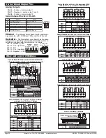
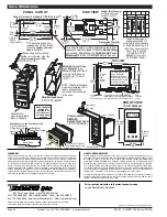
Analog Outputs
Pin 16
–
Positive (+) analog output 1.
Pin 17
–
Negative (
–
) analog output 1 and 2.
Pin 18
–
Positive (+) analog output 2.
Serial Outputs RS-232 or RS-485
Pin No.
19
20
21
22
23
24
RS-232
RS-485
Reserved for future use
RXD. Received Serial
TXD. Transmitted Serial
+5 VDC to power external converters
Isolated Ground
Reserved for future use
B (Low)
A (High)
+5 VDC to power external converters
Isolated Ground
Reserved for future use
Reserved for future use
C
a
rr
i
e
r
B
oa
r
d
O
u
t
pu
t
P
i
n
s
Order Code
OR45
OR46
Options
SP6
SP5
SP4
SP3
SP2
SP1
5A
5A
5A
5A
5A
5A
5A
5A
5A
5A
5A
-
32
31
30
28
29
27
26
25
SP3 SP2 SP1
SP4
SP5
SP6
Relay Modules with five or six 5A Form A Relays
32
31
30
28
29
27
26
25
Options
5A
5A
Order Code
OR11
OR12
OR23
OR14
-
-
-
-
-
-
-
5A
5A
5A
5A
10A
-
-
OR15
OR16
SP2
SP4
SP1
SP3
10A
10A
10A
10A
10A
10A
10A
10A
SP3
SP1
SP4
SP2
Relay Modules with up to two 5A Form A Relays,
and up to two 10A Form C Relays
32
31
30
28
29
27
26
25
Options
Order Code
OR51,
OR61
OR52,
OR62
OR53,
OR63
OR54,
OR64
-
-
-
-
-
-
210mA,
140mA
210mA,
140mA
210mA,
140mA
210mA,
140mA
210mA,
140mA
210mA,
140mA
210mA,
140mA
210mA,
140mA
210mA,
140mA
210mA,
140mA
SP4
SP3
SP2
SP1
SP4
SP3
SP2
SP1
Relay Modules with up to 4 Independent 400V
(210mA DC only) or (140mA AC/DC) SSRs
32
31
30
28
29
27
26
25
Options
Order Code
OR31
OR32
OR33
OR34
-
-
-
-
-
-
5A
5A
5A
5A
5A
5A
5A
5A
5A
5A
SP4
SP3
SP2
SP1
SP1
SP2
SP3
SP4
Relay Modules with up to four 5A Form A Relays
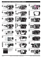
Ethernet
–
The Ethernet carrier board has the same ana-
log output pins, with 10/100Base-T Ethernet (RJ-45 Socket).
DeviceNet
–
The DeviceNet carrier board has the same
analog pinouts, but with a 3.5mm Pitch Socket. The serial out-
put pins are replaced with DeviceNet pins, as follows:
Pin 19 - Positive (+) 24V.
Pin 20 - Can + (positive).
Pin 21 - N/C.
Pin 22 - Can - (negative).
Pin 23 - Negative (-) 24V.
21 20
22
19 18 17 16
23
DeviceNet
Option
Analog
Output
Order Code
OR71
OR72
Options
SP6
SP5
SP4
SP3
SP2
SP1
0 to 5V
0 to V+
0 to 5V
0 to V+
0 to 5V
0 to V+
0 to 5V
0 to V+
0 to 5V
0 to V+
0 to 5V
0 to V+
Open Collector / TTL / 5V Output
32
31
30
28
29
27
26
25
SP1
+5V
V+
ISO
GND
SP3 SP2
SP4
SP6 SP5
Order Code
NPN Open Collector
Max 50V @ 100mA
Sink/Source
OR81
OR82
Options
Setpoint
MACRO Setpoint
Logic Input
6 Outputs
6 Outputs
6 Inputs
6 Inputs
10 MACRO Outputs
-
Opto Isolated I/0 Module for External Breakout Box
with 6 Outputs & 6 Inputs, or 16 Outputs & 6 Inputs
2
4
6
8 10
12
26
24
22
20
18
16
14
1
3
5
7
9
11
25
23
21
19
17
15
13
Logic Input Ground
Ext. 24VDC Supply
for Logic Input
For Sink Connect 23 to 25
For Source Connect 24 to 25
26 Pin
0.1" Centers
1
2
25
26
Setpoints
Setpoints
MACRO Setpoints
1
+
+
-
-
1----TO----6
1----TO----6
Logic Inputs
2
3 4
5 6
1 2
3 4 5 6
MACRO Setpoints
Logic Inputs
7 8
9 10 11 12 13 14 15 16
+
–
Max 50V @ 100mA
Max 50V @ 100mA
Setpoint
Ground
+5V
1----TO----6
1----TO----6
7------------TO-----------16
7------------TO-----------16
Isolated
18VDC
Remove
Both
Jumpers
when using
24VDC
Supply
2V
2V
22K
22K
R
e
l
a
y
a
nd
L
ogi
c
I
/
O
M
o
du
l
e
s
22 21 20
23
19
24
Serial Output
RJ-6 Socket
Order Code
Removable Flash Memory Card
Two NPN Open Collector Outputs
Max 50V @ 100mA
OR91
Options
Flash Card Memory Module
MODULE WITH 4 MEG MEMORY
SP2
SP1
3.5mm Pitch
Screw Terminal


