


Page 15
6/23/04 DI-50B51 320 Series (NZ306)
Texmate, Inc. Tel. (760) 598-9899
•
www.texmate.com
Setpoint Lockout Switch
When the SETPOINT LOCKOUT switch is set to position 1, the
setpoints can be programmed. Once the setpoint values have
been entered and the SETPOINT LOCKOUT switch set to the
ON position, the setpoints can be viewed but not changed.
See Display PLB without Faceplate and Bezel diagram.
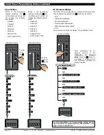
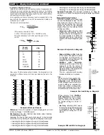
Error Message [Error]
Error messages usually occur during
calibration procedures. The three most
likely causes of an error message are:
1) The full scale and zero signals were
too similar.
Note, the high input (full scale) signal
must be at least 1000 counts greater
than the low input (zero) signal (posi-
tive and negative values are allowed).
2) The scaling requirement exceeded
the capability of the meter (
–
19999 to
+99999).
3) No input signal present, or incorrect
connections.
80
100
90
70
60
50
40
30
20
10
0
SP
SP
6
5
4
3
2
1
Display Showing
Error
Message
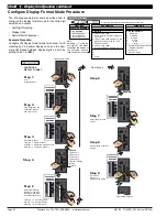
Program Lockout Switch
When the PROGRAM LOCKOUT switch is set to position 2, all
programmable meter functions can be changed.
When set to the ON position, the PROGRAM LOCKOUT switch
prevents any programming changes being made to the meter. If
programming is attempted, the meter displays [LOC]. The ON
position allows programming parameters to be viewed but not
changed.
See Display PLB without Faceplate and Bezel diagram.
80
100
90
70
60
50
40
30
20
10
0
SP
SP
6
5
4
3
2
1
Display Showing LoCK Message
Test Pin
Configure Code 9 to [0XX]. When the TEST pin (pin 10) is con-
nected briefly to the COMMON pin (pin 11) all segments of the dis-
play and setpoint annunciators light up. Six eights and six decimal
points (8.8.8.8.8.8.) are displayed for a short period. The micro-
processor is also reset during this time, losing all RAM settings
such as peak and valley, and any digital input pin settings set up in
Code 9.
The TEST pin can also be configured in Code 9 to carry out the fol-
lowing (see
Meter Programming Codes
on Page 17):
•
Reset counter channel 1 and total 2 at power-up [1XX].
•
Reset counters, CH1, CH2, CH3, CH4, total 1, and total 2 at
power-up [2XX].
•
Reset total 1 and total 2 at power-up [3XX].
Capture Pin
When the CAPTURE pin (pin 12) is connected to the COMMON
pin (pin 11), the CAPTURE pin can be programmed for
setpoint/relay activation or macro control applications in the set-
point control settings mode of the setpoint programming mode
[SPC
—
X] [X2X] .
Common Pin
To activate the LOCK, HOLD, TEST and CAPTURE pins from the
rear of the meter, the respective pins have to be connected to the
COMMON pin (pin 11).
The LOCK pin can also be configured in Code 9 to carry out the fol-
lowing functions (see
Meter Programming Codes
on Page 17):
•
Reset channel 1 [XX1].
•
Reset channel 2 [XX2].
•
Reset channel 3 [XX3].
•
Reset channel 4 [XX4].
•
Reset tare [XX5].
•
Reset total 1 [XX6].
•
Unlatch (de-energize) all setpoints [XX7].
Hold Pin
Configure Code 9 to [X0X]. When the HOLD pin (pin 9) is connect-
ed to the COMMON pin (11) the displayed reading is frozen.
However, A/D conversions and all control functions continue and as
soon as pin 9 is disconnected from pin 11 by the switch, the updat-
ed reading is instantly displayed.
The HOLD pin can also be configured in Code 9 to carry out the fol-
lowing functions (see
Meter Programming Codes
on Page 17):
•
Reset channel 1 [X1X].
•
Reset total 1 and total 2 [X2X].
•
Reset total 2 [X3X].
•
Reset peak and valley [X4X].
•
Reset tare [X5X].
•
Set tare [X6X].
•
Unlatch (de-energize) all setpoints [X7X].
The main programming mode can be entered, but only the bright-
ness setting adjusted. After adjusting the brightness setting, pressing
the
button displays [LoCK].
P
Lock Pin
By configuring Code 9 to [XX0],
connecting the LOCK pin (pin 8 on
the main PCB) to the COMMON
pin (pin 11 on the main PCB), locks
out the main and setpoint program-
ming modes. All meter program-
ming codes and setpoints can be
viewed but not changed.
C
o
n
t
r
ol
s
a
nd
I
nd
i
c
at
o
r
s
C
o
n
t
r
ol
s
a
nd
I
nd
i
c
at
o
r
s
c
o
n
ti
nu
e
d
32
31
30
29
28
27
26
25
17
16
14
15
8
9
10
11
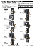
Input Module
(See I-Series Input Module
Guide for Connection Details)
1
2
3
4
5
6
22 21 20
23
18
12
AC/DC POWER
Dual Analog
Output ONLY
19
24
Relay Outputs
Serial Output
Function Pins
LOCK
HOLD
TEST
COM CAPTURE
Analog Output
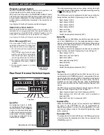
TEST
Rear Panel
COMMON
HOLD
LOCK
CAPTURE
Rear Panel External Switched Inputs


