


Texmate, Inc. Tel. (760) 598-9899
•
www.texmate.com
Page 14
6/23/04 DI-50B51 320 Series (NZ306)
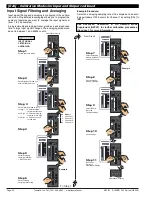
P
UP
Button
DOWN
Button
PROGRAM
Button
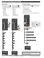
Display with Faceplate and Bezel
LED Annunciators
for Setpoints 1-6
Program Button
While programming, pressing the
button saves the current pro-
gramming settings and moves to the next programming step.
You can move through the programming codes using the program
button. The codes you pass are not affected, unless you stop and
make changes using the
or
buttons.
Pressing the
and
button at the same time initiates the
main programming mode
. To save a new configuration set-
ting and return to the operational display, press the
button
once and then press the
and
button at the same
time.
Pressing the
and
button at the same time initiates the
setpoint programming mode
. To save a new configuration
setting and return to the operational display, press the
but-
ton once and then press the
and
button at the
same time.
See Display with Faceplate and Bezel diagram.
Up Button
When setting a displayed parameter during programming, press
the
button to increase the value of the displayed parameter.
When in the operational display, pressing the
button initiates
a viewing mode that allows you to view the readings on
chan-
nels 1 and 3, setpoints 1, 3, and 5, peak, and total 1
. Once
into the viewing routine, pressing the
button moves through each
displayed parameter.
See Display with Faceplate and Bezel diagram.
Down Button
When setting a displayed parameter during programming, press
the
button to decrease the value of the displayed parameter.
When in the operational display, pressing the
button initiates
a viewing mode that allows you to view the readings on
chan-
nels 2 and 4, setpoints 2, 4, and 6, valley, and total 2
. Once
into the viewing routine, pressing the
button moves through each
displayed parameter.
See Display with Faceplate and Bezel diagram.
Annunciator LEDs
The annunciator LEDs can be programmed to indicate the
alarm status.
Setpoint 1 can be configured to indicate the
rising
signal trend.
Setpoint 2 can be configured to indicate the
falling
signal trend.
They are labeled from left to right: SP1, SP2, SP3, SP4, SP5,
SP6.
See Display with Faceplate and Bezel diagram.
LED Display
The meter has one 5-digit, 7-segment, 8 mm standard red or
optional green LED display. The digital display is the primary
P
P
P
P
P
P
P
display and reads the primary input signal on Channel 1. It is
also used to display all meter configuration programming
codes.
Bargraph Display
The bargraph display is a 51 segment red or green bargraph
that can display the signal from any of four channels or the
result of a processed input signal. The bargraph display is
known as the secondary display during programming.
See Ordering Information for further details.
80
100
90
70
60
50
40
30
20
10
0
SP
SP
6
5
4
3
2
1
Operational Display
Primary Display
Seven
Segment
LED
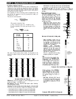
Display
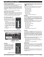
Display PCB without
Faceplate and Bezel
O
N
1
2
SETPOINT
LOCKOUT
Switch
PROGRAM
LOCKOUT
Switch
C
o
n
t
r
ol
s
a
nd
I
nd
i
c
at
o
r
s
C
o
n
t
r
ol
s
a
nd
I
nd
i
c
at
o
r
s
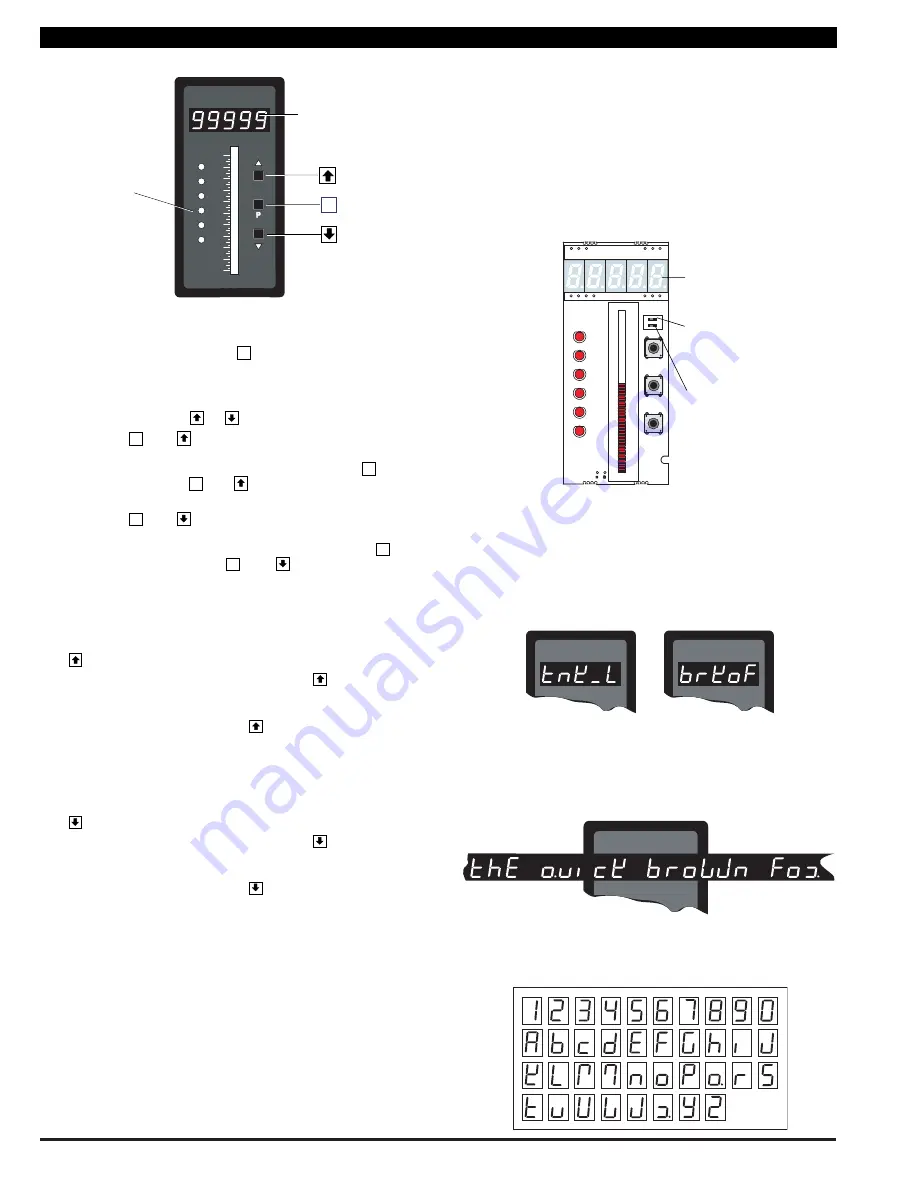
Display Text Editing with 7 Segment
Alphanumeric Display Characters
Display text, such as setpoints, can be easily edited to suit your
application, by connecting the meter to a PC running the free
downloadable Configuration Utility program.
For Example:
Instead of [SP_1]
could be used for
TANK LOW
Instead of [SP_2]
could be used for
BRAKE OFF
OR
Scrolling Display Text Messaging
Scrolling display text messaging can be configured to run but
requires a simple compiler generated macro.
Display Text Characters
The following text characters are used with the 7-segment display.
7-SEGMENT DISPLAY CHARACTERS


