


Section 11 TECHNICAL INFORMATION
212
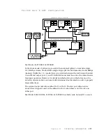
Front Panel: Audio
Balanced audio arrives at AUDIO+/AUDIO- and is converted to single- ended by U16A.
One half of the dual digi- pot, U12 controls the gain of this signal. The other half of this
pot gets a signal from the 87C51 processor via U4 and an analog low- pass smoothing
network consisting of R22,23, C4,6. This is the source of button click audio. The two
signals are summed in U16B and amplified by U17. The loudspeaker is located behind
the dial buttons, which have enough “slop” in their panel holes to permit the audio to
pass without tooooo much resistance.
Front Panel: Processor and Digital
The front panel communicates with the motherboard via an RS- 485 balanced serial
data link. The 87C51 has an internal serial UART subsection. Pushbuttons and LEDs are
interfaced in multiplexed form and converted to/from appropriate serial commands.
U8 - 11 are the LED column drivers, while U15 is the row driver. The LCD contrast and
backlight are controlled by the 87C51 through a digi- pot.
The 87C51 is monitored by a watchdog timer in U13. In the event of software failure
(perhaps due to static electricity, or bad hardware) U13 will not have “activity” on pin
11- the front panel’s equivalent to the motherboard’s DOGSTRB signal. U13 will then
attempt to reset the 87C51 via pin 12.
U13 is also the battery backup controller for the 87C51. At the onset of powering down
the Zephyr U13 forces the 87C51 into a low- current “stand- by” mode. In this mode the
whole front panel only draws a few microamps, and can safely be driven by the
motherboard’s lithium battery. Once the main 5- volt power falls below 3 volts, U13
switches to battery power, maintaining the memory in the 87C51.
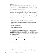
The lower four output bits of U3 contain the master scan counter which controls the
anode/column half of the LED matrix, the one- of- eight input to the keyboard matrix,
and the serial clock to the digi- pots. As this counter cycles through its
possible states the cathode/row half of the LED matrix is set appropriately, the four
outputs from the keyboard matrix are read in, and the data (if any) is clocked out to the
digi- pots. If there is a problem with the scan counter, all three functions will be lost –
the LEDs, the keyboard, and control over the digi- pots.
IMPORTANT WARNING!
If the front panel is disconnected from the motherboard, then
re-connected, the 87C51 will no longer be in “stand-by” mode
and will attempt to draw normal operating current–this can
completely drain the motherboard’s battery in a matter of days!
The proper sequence for re-connecting the front panel
includes powering up the Zephyr immediately after making the
front panel-motherboard connection, then powering down. This
is the only way to put the 87C51 into the proper “stand-by”
mode!
Содержание Zephyr
Страница 13: ...Table of Contents 13 SECTION 1 QUICK RESULTS ...
Страница 26: ...Section 2 INTRODUCTION 26 This page intentially left blank ...
Страница 27: ...Section 2 INTRODUCTION 27 SECTION 2 INTRODUCTION ...
Страница 38: ...Section 2 INTRODUCTION 38 This page intentionally left blank ...
Страница 39: ...39 SECTION 3 ZEPHYR AT A GLANCE ...
Страница 52: ...Section 4 INSTALLATION BASIC OPERATION 52 This page intentionally left blank ...
Страница 53: ...Section 4 INSTALLATION BASIC OP 53 SECTION 4 INSTALLATION BASIC OPERATION ...
Страница 84: ...Section 4 INSTALLATION BASIC OPERATION 84 ...
Страница 85: ...Section 5 ISDN 85 SECTION 5 ISDN ...
Страница 105: ...Section 6 NON ISDN NETWORKS 105 SECTION 7 AUDIO CODING ...
Страница 118: ...Section 7 AUDIO CODING PRINCIPLES 118 This page intentionally left blank ...
Страница 119: ...Section 8 DETAILED MENU REFERENCE 119 SECTION 8 DETAILED MENU REFERENCE ...
Страница 157: ...Section 9 REMOTE CONTROL 157 SECTION 9 REMOTE CONTROL ...
Страница 176: ...Section 9 REMOTE CONTROL 176 This page intentionally left blank ...
Страница 177: ...Section 10 ADVANCED PROBLEM SOLVING 177 SECTION 10 ADVANCED PROBLEM SOLVING ...
Страница 196: ...Section 10 ADVANCED PROBLEM SOLVING 196 This page intentionally left blank ...
Страница 197: ...Section 11 TECHNICAL INFORMATION 197 SECTION 11 DETAILED TECHNICAL INFORMATION ...
Страница 219: ...Section 12 SCHEMATICS 219 SECTION 12 SCHEMATICS ...
Страница 221: ...Section 13 MANUFACTURER S DATA SHEETS 221 SECTION 13 MANUFACTURER S DATA SHEETS ...
Страница 223: ...Section 14 SPECIFICATIONS WARRANTY 223 SECTION 14 SPECIFICATIONS AND WARRANTY ...
Страница 228: ...228 This page intentionally left blank ...
Страница 229: ...Section 15 APPENDICES 229 SECTION 15 APPENDICES ...
Страница 239: ...Section 15 APPENDICES 239 You Com L3 Mono L3 Stereo L2 Mono yes L2 Stereo yes L2 M128 yes G 722 yes ...
Страница 257: ...Section 15 APPENDICES 257 1 Two SPID numbers depending upon number of active B channels 2 Two Directory Numbers ...


