


Section 11 TECHNICAL INFORMATION
211
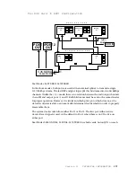
and outputs. The digi- pots, CODEC, Xilinx chips, and analog switches are controlled by
some outputs from this chip, while inputs are taken from the LIMIT and PLL circuits for
subsequent processing and display by the CPU.
U4 is the main system program store EPROM, and U8 is the main system RAM, with a
capacity of 32 K bytes. Chip select for these is generated directly by the 801C88. U5 - 7
are EPROMS which are used for storage of software for the DSPs, and the Xilinx chips. As
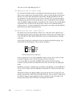
there is not enough address space available from the CPU for all that is required, we use
two bank select lines, BANKSW0 and BANKSW1 to map the 512 K bytes from the
EPROMs into 128 K byte slots available. These line normally have activity only during
XILINX and/or DSP downloads.
U12 provides further segmentation of the processor’s *PCS1 line for application
to the DSPs. It also generates a periodical DOGSTRB signal for U11, the watchdog chip.
The watchdog resets the CPU in the event that the DOGSTRB signal stops. (The
DOGSTRB is generated by software when it is properly operating. When it “hangs,” the
strobe signal is no longer produced, and the dog goes into action.) U11 provides another
function: It connects the battery to the RAM when system power goes away. This is how
the RAM is able to retain data when the unit is powered- down. The chip select for the
RAM is also routed through this chip, in on pin 13, out on pin 12, for protection – when
power looks to be unreliable, the chip select is gated off, preventing any random
memory- destroying writes.
Don’t remove the processor from its socket without the proper removal tool, as this
may damage the socket and the MPU itself.
(Use PLCC extraction tool from AMP, Cat.
No. 821566- 1, or the lower cost No. 822154- 1. Available from Digi- Key at
1.800.344.4539.)
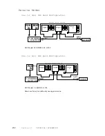
Motherboard A-F: Power Supply
Two three- terminal regulators, VR1,2, provide clean power to the A/D and D/A chips.
Input voltage is ±12Vdc and output is ±5Vdc.
Motherboard A-F: Parallel I/O
U16 accepts the parallel inputs from the “outside world,” and presents them as proper
logic signals to the UART parallel input pins. This chip can take inputs up to 30 Vdc. The
resistor and diode arrangement on the input allow use with voltages or closures from
the driving equipment.
The ULN- 2003A, U15 is a multiple open- collector darlington driver. It converts the
logic signals from the UART’s parallel outputs to open- collector’s to ground for the
outside world. These have high current drive capability – 500 ma per package.
DSP Cards
The DSP cards use surface- mount technology in order to achieve high density.
Therefore, field servicing of these cards is not supported.
Содержание Zephyr
Страница 13: ...Table of Contents 13 SECTION 1 QUICK RESULTS ...
Страница 26: ...Section 2 INTRODUCTION 26 This page intentially left blank ...
Страница 27: ...Section 2 INTRODUCTION 27 SECTION 2 INTRODUCTION ...
Страница 38: ...Section 2 INTRODUCTION 38 This page intentionally left blank ...
Страница 39: ...39 SECTION 3 ZEPHYR AT A GLANCE ...
Страница 52: ...Section 4 INSTALLATION BASIC OPERATION 52 This page intentionally left blank ...
Страница 53: ...Section 4 INSTALLATION BASIC OP 53 SECTION 4 INSTALLATION BASIC OPERATION ...
Страница 84: ...Section 4 INSTALLATION BASIC OPERATION 84 ...
Страница 85: ...Section 5 ISDN 85 SECTION 5 ISDN ...
Страница 105: ...Section 6 NON ISDN NETWORKS 105 SECTION 7 AUDIO CODING ...
Страница 118: ...Section 7 AUDIO CODING PRINCIPLES 118 This page intentionally left blank ...
Страница 119: ...Section 8 DETAILED MENU REFERENCE 119 SECTION 8 DETAILED MENU REFERENCE ...
Страница 157: ...Section 9 REMOTE CONTROL 157 SECTION 9 REMOTE CONTROL ...
Страница 176: ...Section 9 REMOTE CONTROL 176 This page intentionally left blank ...
Страница 177: ...Section 10 ADVANCED PROBLEM SOLVING 177 SECTION 10 ADVANCED PROBLEM SOLVING ...
Страница 196: ...Section 10 ADVANCED PROBLEM SOLVING 196 This page intentionally left blank ...
Страница 197: ...Section 11 TECHNICAL INFORMATION 197 SECTION 11 DETAILED TECHNICAL INFORMATION ...
Страница 219: ...Section 12 SCHEMATICS 219 SECTION 12 SCHEMATICS ...
Страница 221: ...Section 13 MANUFACTURER S DATA SHEETS 221 SECTION 13 MANUFACTURER S DATA SHEETS ...
Страница 223: ...Section 14 SPECIFICATIONS WARRANTY 223 SECTION 14 SPECIFICATIONS AND WARRANTY ...
Страница 228: ...228 This page intentionally left blank ...
Страница 229: ...Section 15 APPENDICES 229 SECTION 15 APPENDICES ...
Страница 239: ...Section 15 APPENDICES 239 You Com L3 Mono L3 Stereo L2 Mono yes L2 Stereo yes L2 M128 yes G 722 yes ...
Страница 257: ...Section 15 APPENDICES 257 1 Two SPID numbers depending upon number of active B channels 2 Two Directory Numbers ...


