


Section 11 TECHNICAL INFORMATION
210
•
Pin 10 should be a constant DC voltage (with just a little ripple, maybe) at some
value between 1.5 and 6 Volts. A voltage at or near either ground or the 7.6 V
positive rail is indication of trouble.
•
Pin 3 and 14 should have clock signals which are the same frequency and in- phase,
locked to each other.
•
Pin 1 should be high.
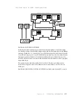
Motherboard A-F: System Clock
System clock for the CPU and DSPs is generated by U19, a packaged oscillator,
operating at 50 MHz. U20 divides this to the various frequencies required. Sections of
U18 buffer the 50 MHz signal for driving the DSP chips.
Motherboard A-F: Xilinx
The two Xilinx chips, LCA1 and LCA2, are general purpose logic chips which
are loaded with software from the CPU in order to determine their operation
characteristics. Software is downloaded serially via XLNX- DIN (DataIN) and XLNX-
CCLK (bit CLK).
Once configured these chips make all the serial “pipeline” connections among
the DSPs and provide the switching and routing function to the selected digital interface
(V.35/ISDN/etc.), as described in Section 5.2. Both local and network reference clocks
are also generated within the Xilinx chips.
Since many of the DSP connections to the Xilinx chips are also software- configurable,
and since these connections depend on the specific operating mode, Xilinx pins may
sometimes be inputs but at other times outputs. This is different from bi- directional
pins because the hardware surrounding each Xilinx pin is set by software to be either
one way or the other
on a per- configuration basis
.
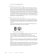
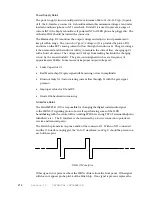
For troubleshooting purposes the most informative signal to look at is the
DONE/*PROG signal on pin 55 of each LCA (on the right- hand side of the chip as you
look at the part number, second pin from the bottom). This pin should be low during
the software download period (at powerup and during some mode changes), and will go
high as the chip becomes operational. If there is a problem with the download process
or the chip itself, this pin will remain low – and the chip will remain inactive.
Motherboard A-F: Microprocessor and Peripherals
The CPU and peripherals are a fairly straightforward, textbook Intel 801C88 processing
system. U1 is the CPU, U3,46 provided data/address bus de- muxing,
U2 is a buffer for the data bus. U17 buffers some of the other signals.
The UART, U9 and PIO, U10 are standard peripherals, using the 801C88’s internal chip
selects for access. The UART is dual, and handles both the RS- 232 port and
the front panel RS- 485 connection via suitable drivers, U13/16 and U14, respectively.
Some of the UART’s pins can be configured as parallel inputs or outputs and are used
for various I/Os. The 8255 is for additional parallel inputs
Содержание Zephyr
Страница 13: ...Table of Contents 13 SECTION 1 QUICK RESULTS ...
Страница 26: ...Section 2 INTRODUCTION 26 This page intentially left blank ...
Страница 27: ...Section 2 INTRODUCTION 27 SECTION 2 INTRODUCTION ...
Страница 38: ...Section 2 INTRODUCTION 38 This page intentionally left blank ...
Страница 39: ...39 SECTION 3 ZEPHYR AT A GLANCE ...
Страница 52: ...Section 4 INSTALLATION BASIC OPERATION 52 This page intentionally left blank ...
Страница 53: ...Section 4 INSTALLATION BASIC OP 53 SECTION 4 INSTALLATION BASIC OPERATION ...
Страница 84: ...Section 4 INSTALLATION BASIC OPERATION 84 ...
Страница 85: ...Section 5 ISDN 85 SECTION 5 ISDN ...
Страница 105: ...Section 6 NON ISDN NETWORKS 105 SECTION 7 AUDIO CODING ...
Страница 118: ...Section 7 AUDIO CODING PRINCIPLES 118 This page intentionally left blank ...
Страница 119: ...Section 8 DETAILED MENU REFERENCE 119 SECTION 8 DETAILED MENU REFERENCE ...
Страница 157: ...Section 9 REMOTE CONTROL 157 SECTION 9 REMOTE CONTROL ...
Страница 176: ...Section 9 REMOTE CONTROL 176 This page intentionally left blank ...
Страница 177: ...Section 10 ADVANCED PROBLEM SOLVING 177 SECTION 10 ADVANCED PROBLEM SOLVING ...
Страница 196: ...Section 10 ADVANCED PROBLEM SOLVING 196 This page intentionally left blank ...
Страница 197: ...Section 11 TECHNICAL INFORMATION 197 SECTION 11 DETAILED TECHNICAL INFORMATION ...
Страница 219: ...Section 12 SCHEMATICS 219 SECTION 12 SCHEMATICS ...
Страница 221: ...Section 13 MANUFACTURER S DATA SHEETS 221 SECTION 13 MANUFACTURER S DATA SHEETS ...
Страница 223: ...Section 14 SPECIFICATIONS WARRANTY 223 SECTION 14 SPECIFICATIONS AND WARRANTY ...
Страница 228: ...228 This page intentionally left blank ...
Страница 229: ...Section 15 APPENDICES 229 SECTION 15 APPENDICES ...
Страница 239: ...Section 15 APPENDICES 239 You Com L3 Mono L3 Stereo L2 Mono yes L2 Stereo yes L2 M128 yes G 722 yes ...
Страница 257: ...Section 15 APPENDICES 257 1 Two SPID numbers depending upon number of active B channels 2 Two Directory Numbers ...


