background image

27

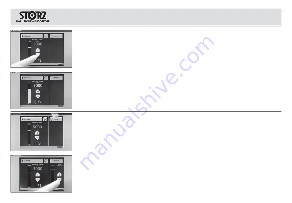
2.3 Maximale Drehzahl (Sollwert) vorwählen

Das linke Feld des Arbeitsbildschirms dient der
Einstellung und Anzeige der Motordrehzahl. Der
zur Verfügung stehende Drehzahlbereich wird an
der linken Balkenanzeige unten und oben ange-
zeigt (hier 300 – 7000 U/min). Mittels der „+/–“
Tasten kann die Maximaldrehzahl (Sollwert) vor-
gewählt werden. Diese vorgewählte Drehzahl
wird mittels der roten Ziffern und des weißen
Striches in der Balkenanzeige angezeigt.

Hinweis: 

Der „Einschaltstartwert“ für die max.

Drehzahl ist 3000 U/min oder weniger!

2.3 Select the maximum speed (set value)

The left-hand field on the operation screen is
used for setting and displaying the motor rpm.
The available speed range is displayed in the
top and bottom of the left-hand bar indicator
(300 to 7,000 rpm in this instance). The maxi-
mum speed (set value) can be selected with the
“+/–” buttons. This selected speed is displayed
with the red numbers and the white line in the
bar indicator.

Note: 

The “Initialization start value” for the max.

speed is 3,000 rpm or less!

2.3 Выбрать максимальную скорость вра-
щения (заданное значение)

Левое поле рабочего экрана служит для нас$

тройки и показа скорости вращения мотора.

Возможный диапазон скорости вращения пока-

зывается на левом штриховом индикаторе

внизу и вверху (в примере 300–7000 об/мин.).

Исполюзуя кнопки «+/$» можно теперь выбрать

макс. скорость вращения (заданную величину).

Предварительно выбранная скорость вращения

отображается красными цифрами и белой чер-

той на штриховом индикаторе.

Указание:

«Начальное стартовое значение»

макс. скорости вращения 3000 об/мин. или
меньше!

Wird das „Handstück“ durch Betätigen des rech-
ten Fuß schalterpedals eingeschaltet, werden die
Balken anzeige und die Ziffern der Drehzahl -
anzeige grün und zeigen die aktuelle Drehzahl
an (Istwert). 

If the “Handpiece” is switched on by activating
the right-hand footswitch pedal, the bar indicator
and the numbers in the speed display turn green
and show the current speed (actual value). 

Если «рукоятка» приводится в действие с
помо$щью правой педали ножного переключа-
теля , то штриховой индикатор и показывающие
скорость вращения цифры становятся зеле-
ными, и они показывают актуальную скорость
вращения (фактическое значение)

2.4 Kühl- und Spülpumpe konfigurieren 

In allen Betriebsmodi (außer „DERMATOME“)
kann optional die integrierte Kühl- und Spül -
mittelpumpe aktiviert werden. Zur Aktivierung
muss im rechten Feld des Arbeitsbildschirms die
Taste „PUMPE“ angetippt werden. 

Hinweis: 

Informationen zur Einstellung der

Spülpumpe finden Sie auf Seite 16.

2.4 Configuring the cooling and irrigation

solution pump 

In every operating mode (with the exception of
“DERMATOMES”), the integrated cooling and
irrigation solution pump can be activated as an
option. Press the “PUMP” button in the right-
hand field of the operation screen to activate it. 

Note: 

F

or

information on configuring the irriga-

tion pump, see page 16.

2.4 Сконфигурировать насос 

для охлаждения и промывания

При всех режимах работы (за исключением
«ДЕРМАТОМЫ») можно активировать по жела-
нию встроенный насос для охлаждения и про-
мывания. Для его активирования использовать
кнопку «PUMP» (НАСОС), расположенную в
правом поле рабочего экрана. 

Указание: 

Информацию о настройке насоса

Вы найдете на стр. 16

.

Ist die Pumpe aktiv, wird in der Schaltfläche ein
grüner Punkt, und darunter die graphische
Balken anzeige der Spülflussanzeige einge -
schaltet. 
Der Spülfluss kann mittels der „+/– Tasten“ 
voreingestellt werden (Sollwert). 
Der Sollwert wird durch den weißen Strich in der
Balkenanzeige dargestellt. 

If the pump is active, a green dot appears in the
button and the graphic indicator for the irrigation
flow quantity is switched on below. The irrigation
flow can be set with the “+/– buttons” (set
value). The set value is indicated by the white
line in the bar indicator. 

Если насос активирован, то на рабочей
поверх$ности появляется зеленая точка, а
затем вклю$чается графический штриховой
индикатор.
Промывочный поток может быть предварительно
установлен с помощью кнопки «+/$» (заданное
значение). Заданное значение показано белой
чертой на штриховом индикаторе

Installation and 
operating instructions

SHAVER

Aufstellen und
Bedienungshinweise

SHAVER

Установка и 
указания по обслуживанию

ШЕЙВЕР

Содержание 20711620-1

Страница 1: ...UNIDRIVE ENT NEURO OMFS UNIDRIVE ENT NEURO OMFS UNIDRIVE ENT NEURO OMFS 20711x 20 1 20711x 20 1 20711x 20 1 x 6 x 7 x 8...

Страница 2: ......

Страница 3: ...Gebrauchsanweisung Instruction Manual UNIDRIVE ENT NEURO OMFS UNIDRIVE ENT NEURO OMFS UNIDRIVE ENT NEURO OMFS 20711x 20 1 20711x 20 1 20711x 20 1 x 6 x 7 x 8...

Страница 4: ...organization have decided in favor of a modern high quality piece of equipment from KARL STORZ This instruction manual is intended as an aid in setting up connecting and operating the UNIDRIVE ENT NEU...

Страница 5: ...III Ger teabbildungen Photographs of the equipment...

Страница 6: ...IV...

Страница 7: ...zeige von Ger teparametern Power switch for turning the unit on and off TFT Touch screen Connector for motor handpiece M1 Connector for motor handpiece M2 Irrigation pump Clamp for irrigator stand Con...

Страница 8: ...pollution control China RoHS 1 2 BF RoHS M1 GEFAHR Bei Verwendung z ndf higer Narkosegase in der unmittelbaren Umgebung des Ger tes besteht Explosionsgefahr VORSICHT Ger t nicht ffnen Gefahr eines el...

Страница 9: ...e 53 KARL STORZ II III V VI 3 3 5 5 8 8 9 9 10 10 10 10 KARL STORZ SCB 11 12 12 12 14 17 UNIDRIVE 17 18 19 20 21 1 21 2 25 3 29 4 DRILLCUT X 33 5 37 6 43 7 45 8 48 50 50 53 Wichtiger Hinweis f r die B...

Страница 10: ...hen Vertr glichkeit EMV 81 Garantiekarte Niederlassungen Maintenance 56 Changing the fuse 56 Cleaning disinfection and sterilization 57 Maintenance 62 Service and repair 62 Repair program 63 Limitatio...

Страница 11: ...learly readable operating elements on a color display Pump activated via footswitch 3 Systembeschreibung Das neue KARL STORZ Motorensystem UNIDRIVE ENT NEURO OMFS zeichnet sich durch modernste Elektro...

Страница 12: ...402xx 403xx Micro Shaver handpiece straight 407110 35 with shaver attachment 402xx 403xx STAMMBERGER CASTELNUOVO DrillCut X Shaver Handpiece 407110 40 with shaver attachment 412xx 413xx STAMMBERGER CA...

Страница 13: ...n on the operation of the unit Warnung Lesen Sie diese Gebrauchsanwei sung genau durch bevor Sie das Ger t in Be trieb nehmen Lesen Sie besonders das Kapitel Sicherheitshinweise aufmerksam durch um Ge...

Страница 14: ...gl Medizinprodukte Betreiberverordnung 4 Jedes ffnen des Ger tes durch nichtautorisier te Personen f hrt zum Erl schen der Garantie WARNINGS Warning The UNIDRIVE ENT NEURO OMFS must only be used in me...

Страница 15: ...r tes die auf grund von Fehlbedienungen entstehen fallen nicht unter die Gew hrleistungsanspr che Caution Only operate the unit with the voltage stated on the unit s identification plate Caution When...

Страница 16: ...URO OMFS motor system is universally applicable in conjunction with the respective suitable application instruments in the ENT NEURO OMFS application range The exact Intended use of the application in...

Страница 17: ...t not be operated inside the hazard zone shown in the diagram This also applies for easily combustible and explosive chemicals e g skin disinfectants and fast acting surface disinfectants UNIDRIVE ENT...

Страница 18: ...OMFS 207118 20 1 1 Power cord 400 A 1 Two pedal footswitch with proportional function 200126 30 1 tubing set for irrigation can be sterilized 207116 40 1 Clip Set 207116 21 1 3 pcs mtp Tubing Sets si...

Страница 19: ...T NEURO OMFS on a level surface UNIDRIVE ENT NEURO OMFS Der UNIDRIVE ENT NEURO OMFS ist mit einer Steckvorrichtung f r den Potentialausgleich ausger stet Lassen Sie die Erdung ggf durch sachkundiges P...

Страница 20: ...in der Statuszeile des TFT Displays siehe Pfeil Hinweis Zum Ausstecken des Anschluss kabels am Stecker ziehen nicht am Kabel K hl und Sp lpumpe Die Steuereinheit UNIDRIVE ENT NEURO OMFS ist mit einer...

Страница 21: ...hset z B zur Auf bereitung demontiert worden ist ist es wie nach folgend beschrieben wieder zusammenzusetzen Pumpenschlauch beidseitig bis zum Anschlag auf die Konnektoren aufstecken aufschieben Zulau...

Страница 22: ...lendet Insert the pump tubing Flip the lever for retracting extending the pump roll down into the horizontal position Caution Use only the tubing set that is intended for use with the UNIDRIVE ENT NEU...

Страница 23: ...dem Sp lfl ssigkeitsbeutel Einstichdorn verbinden bzw auf den Sp lanschluss des DrillCut X Shaver Handst cks des Bohrhandst cks bzw der Mikro S ge aufstecken Hinweis Bei Verwendung einer Sp lflasche...

Страница 24: ...i 0 wei er Strich ganz unten siehe auch Fu schalterfunktion 1 5 a b Hinweis Das Einstellen mittels des linken Pedals ist nur bei nicht bet tigtem rechten Pedal m glich d h nicht w hrend des Bohrens od...

Страница 25: ...bar In diesem Fall vorgehen wie im Kapitel Service Modus unter Touch Screenkalibrierung beschrieben siehe S 53 For approx 2 seconds the initialization screen appears on the TFT display as shown on the...

Страница 26: ...t werksseitig mit englischer Anzeigesprache ausgeliefert wird Dazu die Taste MENU rechts unten bet tigen Selecting the language It may be required to define a different language for the operation scre...

Страница 27: ...d this also applies for switching from M2 to M1 Note Switching between M1 M2 is also possible by activating the yellow button on the footswitch for a longer period of time 2 s see also Footswitch func...

Страница 28: ...attachment 413xx Default 12 000 rpm Maximum 6 Intranasal Drill 660000 with EC Micromotor 207110 32 Page 43 INTRANASAL DRILL 3 000 60 000 rpm 7 Microsaw 254000 Micro Sagittalsaw 254100 Page 45 SAWS 1 0...

Страница 29: ...C Mikro motor 207110 32 1 Select the DRILL operating mode INTRA drill handpiece 2524xx with EC Micromotor 20711032 1 INTRA 2524 207110 32 1 1 Betriebsmodus Applikationshandst ck ndern Zum ndern des Be...

Страница 30: ...imum speed when activating the footswitch pedal within a predefined amount of time Select the MEN button in this case 1 2 SOFT START SOFT START KONFIGURATION BOHRER ausw hlen Gew nschte Zeitdauer ausw...

Страница 31: ...rms dient der Einstellung und Anzeige der Motordrehzahl Der zur Verf gung stehende Drehzahlbereich wird an der linken Balkenanzeige unten und oben angezeigt hier 1 000 40 000 U min Mittels der Tasten...

Страница 32: ...Das Handst ck wird gestartet Pumpe auf vorein gestelltem Sp lfluss d gelbe Taste oben kurz antippen nderung der Drehrichtung Hinweis Die Standardeinstellung nach jedem Einschalten bzw Anw hlen des Arb...

Страница 33: ...andst ck zu konfigurieren bitte folgenderma en vorgehen Auf dem Arbeitsbildschirm die Taste MEN anw hlen 2 1 Configuring and selecting the application handpiece SHAVER To configure the selected applic...

Страница 34: ...pplikationshandst ck ndern Zum ndern des Betriebsmodus Auswahl des Applikationshandst cks die Betriebsmodus Taste oben links bet tigen 2 2 Changing the operating mode application handpiece To change t...

Страница 35: ...ivating the right hand footswitch pedal the bar indicator and the numbers in the speed display turn green and show the current speed actual value 2 4 K hl und Sp lpumpe konfigurieren In allen Betriebs...

Страница 36: ...edalstellung Das Handst ck wird gestartet Pumpe auf vorein gestelltem Sp lfluss d gelbe Taste l nger als 2 Sek bet tigt Umschalten zwischen Motorausgang 1 M1 und Motorausgang 2 M2 oder umgekehrt 2 5 F...

Страница 37: ...itte folgenderma en vorgehen Auf dem Arbeitsbildschirm die Taste MEN anw hlen 3 1 Selecting the MICRO SHAVER application handpiece To configure the selected application handpiece please continue as fo...

Страница 38: ...plies for both channels BACK OPERATING MODE OPERATING MODE 3 2 Betriebsmodus Applikationshandst ck ndern Zum ndern des Betriebsmodus Auswahl des Applikationshandst cks die Betriebsmodus Taste oben lin...

Страница 39: ...n the speed display turn green and show the current speed actual value 3 4 K hl und Sp lpumpe konfigurieren In allen Betriebsmodi au er DERMATOME kann optional die integrierte K hl und Sp l pumpe akti...

Страница 40: ...s wieder bei 0 Pumpe stoppt c rechtes Pedal bet tigen dieses Pedal hat eine Proportional Funktion Gaspedal Funktion die Drehzahl variiert in Abh ngigkeit von der Pedalstellung Das Handst ck wird gesta...

Страница 41: ...rieren bitte folgenderma en vorgehen Auf dem Arbeitsbildschirm die Taste MEN anw hlen 4 1 Configuring and selecting the DRILLCUT X application handpiece To configure the selected application handpiece...

Страница 42: ...n screen Note The selected shaver type applies for both channels BACK OPERATING MODE OPERATING MODE 4 2 Betriebsmodus Applikationshandst ck ndern Zum ndern des Betriebsmodus Auswahl des Applikationsha...

Страница 43: ...d display turn green and show the current speed actual value 4 4 K hl und Sp lpumpe konfigurieren In allen Betriebsmodi au er DERMATOME kann optional die integrierte K hl und Sp lpumpe aktiviert werde...

Страница 44: ...bet tigt Umschalten vom Betriebsmodus DRILLCUT X auf SINUSBOHRER oder umgekehrt Diese Funktion muss im Men Fu schalter konfigu rieren aktiviert sein Zur Aktivierung siehe Kapitel 5 6 Bei Umschaltung...

Страница 45: ...electing the application handpiece Note This selection is not required if the hand piece has already been selected as described under section 2 3 or 4 Continue directly with section 5 2 Select the MEN...

Страница 46: ...this case the selected settings are not saved automatically Therefore the operating mode button in the top left must be activated again OPERATING MODE Bei Bet tigung der Taste SINUSBOHRER sind die Ei...

Страница 47: ...le speed range is displayed in the top and bottom of the left hand bar indicator SINUS BURR with DRILLCUT X 800 12 000 rpm 5 3 DRILLCUT X 800 12000 Mittels der Tasten kann nun die Maximal drehzahl Sol...

Страница 48: ...ird durch den wei en Strich in der Balkenanzeige dargestellt If the pump is active a green dot appears in the button and the graphic indicator for the irrigation flow quantity is switched on below The...

Страница 49: ...he following functions in the SINUS BURR operating mode a Activate the left pedal only the pump is activated irrigation flow according to defined value see Activating the pump 5 4 b Short quick actuat...

Страница 50: ...RATION und im danach ffnenden Men die Taste KONFIGURATION FUSSSCHALTER Activate the MENU button to configure the footswitch Then activate the CONFIGURATION and in the menu that is opened activate the...

Страница 51: ...hes back to the operation screen automatically The designation INTRANASAL DRILL can now be read on the operating mode button INTRANASAL DRILL INTRANASAL DRILL 6 2 Maximale Drehzahl Sollwert vorw hlen...

Страница 52: ...gr ner Punkt und darunter die graphische Balkenanzeige der Sp lflussanzeige eingeschaltet Der Sp lfluss kann mittels der Tasten voreingestellt werden Sollwert Der Sollwert wird durch den wei en Strich...

Страница 53: ...ximum value and then the flow quantity begins at 0 again Pump stops c Activate the right pedal this pedal has a proportional function Gas pedal function the speed is varied depend ing on the pedal pos...

Страница 54: ...e operation screen is used for setting and displaying the motor rpm The available speed range is shown in the left hand bar indicator at the top and bottom in this case 1 000 to 20 000 rpm Use the but...

Страница 55: ...n Betrieb genommen startet die Pumpe automatisch mit und f rdert die voreingestellte Sp lmenge Mit dem linken Fu schalterpedal wird nur die Pumpe in Betrieb genommen und die Sp l fl ssigkeit mit dem v...

Страница 56: ...2 Sec Switches between motor output 1 M1 and motor output 2 M2 or vice versa c d e 2 1 1 2 2 8 Betriebsmodus DERMATOME ausw hlen Dermatome 253xxx mit EC Mikromotor 207110 32 8 Selecting the DERMATOMES...

Страница 57: ...d Sp lpumpe konfigurieren Die Funktion der K hl und Sp lpumpe ist im Betriebsmodus DERMATOME nicht verf gbar 8 3 Configuring the cooling and irrigation solution pump The function of the cooling and ir...

Страница 58: ...ted or the yellow button on the footswitch must be activated for longer than 2 Sec UNIDRIVE ENT NEURO OMFS 2 407110 35 407110 39 407110 40 1 1 2 2 2 Werkseinstellungen wiederherstellen Das Ger t wird...

Страница 59: ...VICE ADJUSTMENTS SERVICE ADJUSTMENT Bei der Frage nach dem Passwort mittels Bildschirmtastatur DEFAULT eingeben und mit der ENTER Taste best tigen When queried for the password enter DEFAULT using the...

Страница 60: ...the text line in the top margin and a signal tone is heard as confirmation The factory settings are restored CHANGED TO DEFAULT VALUE Anschlie end das Men ber die Taste BACK ZUR CK oder OPERATING MODE...

Страница 61: ...ngezeigt Im unteren Bereich die Betriebsstunden und die Software Versionsst nde Die Bet tigung der Taste BETRIEB OPERATING MODE f hrt zu der Arbeitsbild schirmseite zur ck von der aus das MEN auf geru...

Страница 62: ...ted This is the case when initializing a new device for the first time for instance I e touching the touch area of the keys has no visible influence To perform the touch calibration on an uncali brate...

Страница 63: ...OOTSWITCH kein Fu schalter angeschlossen E 12 KEIN MOTOR M1 NO MOTOR IN M1 kein Motor Handst ck an M1 angeschlossen E 14 KEIN MOTOR M2 NO MOTOR IN M2 kein Motor Handst ck an M2 angeschlossen In the to...

Страница 64: ...tfernen Sicherungswechsel Die Steuereinheit ausschalten und Netzverbindung trennen Changing the fuse Switch the control unit off and disconnect the power 56 Neue Sicherungen einstecken Netzsicherungsh...

Страница 65: ...ie von KARL STORZ freigegebenen Chemikalien zur Aufbereitung von Medizin produkten siehe Anhang S 79 80 Cleaning disinfection and sterilization Note Pease read the instruction manual provid ed with th...

Страница 66: ...es of the Employer s Liability Insurance Association and equivalent organizations must be observed 1 Disconnect the reusable tubing and immerse it in cleaning solution as per the manufacturer s instru...

Страница 67: ...ken Verunreinigungen der Schl uche ist eine Vorreinigung vor der maschi nellen Aufbereitung erforderlich 3 After cleaning rinse the tubing and place it in a suitable container with disinfectant soluti...

Страница 68: ...lenen Sterilisationsparametern sind vom Anwender zu validieren Assemble tubing set as described in section Preparing the tubing set on p 13 making sure that connections are secure to prevent leakage i...

Страница 69: ...a 3 bar Einwirkzeit 5 Minuten f r alle Instrumente Steam sterilization KARL STORZ has validated the following sterilization method Fractionated prevacuum steam sterilization Warning Tubing sets may on...

Страница 70: ...te To ensure secure operation the following testing should be performed every 12 months 1 Check the leakage current from the chassis 100 A 2 Check the ground impedance 0 1 Ohm 3 Check the power consum...

Страница 71: ...tori sierte Dritte durchgef hrt wurde KARL STORZ KARL STORZ KARL STORZ GmbH Co KG Abt Reparaturservice Dr Karl Storz Str 34 78532 Tuttlingen KARL STORZ KARL STORZ KARL STORZ Repair program Usually to...

Страница 72: ...at all times Manufacturer s warranty For a period of two years after delivery to the end user we shall replace free of charge equip ment that can be proven to have defects in material or workmanship I...

Страница 73: ...Ger test rungen kann der Anwender die Fehlersuchliste in diesem Kapitel zu Hilfe neh men um die m gliche Ursache festzustellen Wie und durch welche Abhilfe diese St rungen behoben werden k nnen ist in...

Страница 74: ...weis Ein neues Handst ck kann nicht sofort am gleichen Kanal verwendet werden 14 E14 KEIN MOTOR M2 siehe E12 siehe E12 15 E15 BERTEMPERATUR MOTOR M2 siehe E13 siehe E13 16 E16 PUMPENKOPF NICHT GESCHLO...

Страница 75: ...ce on 2nd channel Note A new handpiece cannot be used immediately on the same channel 14 E14 NO MOTOR IN M2 see E12 see E12 15 E15 TOO HIGH TEMPERATURE MOTOR M2 see E13 see E13 16 E16 IRRIGATION PUMP...

Страница 76: ...PERATURE MOTOR M1 14 E14 NO MOTOR IN M2 E12 E12 15 E15 TOO HIGH TEMPERATURE MOTOR M2 E13 E13 16 E16 IRRIGATION PUMP NOT CLOSED 17 E17 MOTOR BLOCKED OR WRONG M1 18 E18 MOTOR BLOCKED OR WRONG M2 E17 E17...

Страница 77: ...r electronics Recommended remedy 1 2 4 Notify customer service 3a Connect another handpiece 3b Clean the handpiece 1 2 3 4 1 2 3 3 4 1 2 4 3 3 Problem Instrument v llig funktionsunf hig M gliche Ursac...

Страница 78: ...lower connectors are different sizes 2 Press connectors firmly in the direction of the pump tubing 1 2 1 2 Problem Sp lfl ssigkeit l uft nicht M gliche Ursache 1 Sp lbeutel leer 2 Schlauchklemme verhi...

Страница 79: ...VE NEURO 207117 20 1 UNIDRIVE OMFS 207118 20 1 Line voltage 100 120 230 240 V Power frequency 50 60 Hz Power fuse 2 x T 2 0 AL 250 V IEC 127 Format Power consumption 173 VA Operating temperature 10 40...

Страница 80: ...l 8 000 U min Drehmodus Rotation MICRO SHAVER Minimum speed 150 rpm Maximum speed 3 000 rpm Switch on maximum speed 3 000 rpm Rotation mode Oscillation DRILLCUT X Minimum speed 300 rpm Maximum speed 7...

Страница 81: ...EC 60601 1 2 2001 Observe the information on electromagnetic compatibility in the appendix pages 81 93 Richtlinienkonformit t f r 207116 20 1 207117 20 1 207118 20 1 Medizinprodukt der Klasse IIa Dies...

Страница 82: ...ical documentation On request the manufacturer will provide those circuit diagrams itemized parts listings descrip tions sets of adjustment instructions and other items of available documentation to s...

Страница 83: ...75 Blockschaltbild Block diagram Technische Beschreibung Technical description SCB...

Страница 84: ...l function Tubing Set for irrigation 207116 40 for UNIDRIVE ENT NEURO OMFS reuseable sterilizable Clip Set for tubing set 207116 21 Power line fuse T 2 0 AL 250 V 200110 80 SCB Connecting Cable 200901...

Страница 85: ...nction with High Performance EC Micromotor 207110 32 and Connecting Cable 207110 72 INTRA Drill Handpiece angled 252479 18 cm with burrs Standard Diamond Diamond coarse Rack for 12 5 cm burrs 280034 c...

Страница 86: ...High Performance EC Micromotor 20711032 and Connecting Cable 207110 72 Intranasal Drill 660000 Sterilizing and Storage Basket 39551 A for intranasal drill system In conjunction with High Performance...

Страница 87: ...www karlstorz com Note When agents other than those named are used KARL STORZ assumes no liability for any damage which may occur 1 2 3 A www karlstorz com KARL STORZ Vorsicht Die Verwendung von NATRO...

Страница 88: ...fection have been approved regarding material compatibility KARL STORZ HAMOU IMPERATOR KARL STORZ Ed 09 2006 Typ 1 Reiniger 2 Desinfektionsmittel 3 geeignet f r Ultraschallb der 4 Neutralisator 5 Klar...

Страница 89: ...regarding Electromagnetic Compatibility EMC Observe the EMC instruc tions in this appendix during installation and commissioning The UNIDRIVE ENT NEURO OMFS model 207116 20 1 207117 20 1 207118 20 1...

Страница 90: ...ot be used adjacent to or stacked with other equipment If adjacent or stacked use is necessary the equipment or system should be observed to verify normal operation in the con figuration in which it w...

Страница 91: ...endet HF Energie ausschlie lich zu seiner internen Funktion Daher ist seine HF Aussendung sehr gering und es ist unwahrscheinlich dass benachbarte elektronische Ger te gest rt werden HF Aussendungen n...

Страница 92: ...RIVE ENT NEURO OMFS model 207116 20 1 207117 20 1 207118 20 1 should ensure that it is used in such an environment Emissions test Compliance Electromagnetic environment guidance RF emissions CISPR 11...

Страница 93: ...en von Bildst rungen kann es erforderlich sein die Qualit t der Versorgungsspannung mit einem Netzfilter weiter zu verbessern Sto spannungen Surges nach IEC 61000 4 5 1 kV Gegentaktspannung 2 kV Gleic...

Страница 94: ...age distortion occurs it may be necessary to further filter the power quality by using a AC line filter Surge IEC 61000 4 5 1 kV differential mode 2 kV common mode Complies 1 kV differential mode 2 kV...

Страница 95: ...V 8 kV 6 kV 8 kV 30 IEC 61000 4 4 2 kV 1 kV 2 kV 1 kV IEC 61000 4 5 1 kV 2 kV 1 kV 2 kV IEC 61000 4 11 5 UT 95 UT 1 2 40 UT 60 UT 5 70 UT 30 UT 25 5 UT 95 UT 5 5 UT 95 UT 1 2 40 UT 60 UT 5 70 UT 30 UT...

Страница 96: ...P als Nennleistung des Senders in Watt W gem den Angaben des Senderherstellers und d als empfohlenem Schutzabstand in Metern m Die Feldst rke station rer Funksender sollte bei allen Frequenzen gem ein...

Страница 97: ...d 3 7 800 MHz to 2 5 GHz Where P is the maximum output power rating of the transmitter in watts W according to the transmitter manufacturer and d is the recommended separation in meters m Field streng...

Страница 98: ...8 20 1 EN IEC 60601 UNIDRIVE ENT NEURO OMFS 20 7116 20 1 20 7117 20 1 20 7118 20 1 IEC 61000 4 6 3 Veff 150 80 3 V P d 3 5 3 150 80 IEC 61000 4 3 3 V m 80 2 5 3 P d 3 5 3 80 800 P d 3 7 800 2 5 d b 15...

Страница 99: ...n und dem Ger t abh ngig von der Ausgangsleistung des Kommunikationsger tes wie unten angegeben einh lt Schutzabstand d m abh ngig von der Sendefrequenz Nennleistung des Senders W 150 kHz bis 80 MHz P...

Страница 100: ...and the unit as recommended below according to the maximum output power of the communications equipment Separation distance d m according to frequency of transmitter Rated maximum output power of tran...

Страница 101: ...FS 20 7116 20 1 20 7117 20 1 20 7118 20 1 d 150 80 P d 3 5 3 80 800 P d 3 5 3 800 2 5 P d 3 7 0 01 0 12 0 12 0 23 0 1 0 38 0 38 0 73 1 1 2 1 2 2 3 10 3 8 3 8 7 3 100 12 12 23 d Anhang Hinweise zur ele...

Страница 102: ......

Страница 103: ...arranty referred to in our Standard Conditions of Business shall apply To be completed by the supplier importer Company stamp signature Garantiekarte bei Kauf Lieferung ausf llen lassen und m glichst...

Страница 104: ...erschrift Datum Bitte ausreichend frankieren ANTWORTKARTE KARL STORZ GmbH Co KG Postfach 230 78503 Tuttlingen To be filled out by instrument owner Return address company stamp Field of application Typ...

Страница 105: ......

Страница 106: ...olorian nr 74 Sector 4 041393 Bukarest Romania Phone 40 0 31 4250800 Fax 40 0 31 4250801 E Mail office karlstorz ro TOV KARL STORZ Ukraine 18b Geroev Stallingrada avenu 04210 Kiev Ukraine Phone 380 44...

Страница 107: ......

Страница 108: ...KARL STORZ GmbH Co KG Mittelstra e 8 78532 Tuttlingen Postfach 230 78503 Tuttlingen Germany Telefon 49 0 7461 708 0 Telefax 49 0 7461 708 105 E Mail info karlstorz de Web www karlstorz com...

Отзывы: