ST750
G
ENERAL
H
ANDBOOK
667/HB/33750/000
Page 57
Issue 6
4.11 TC12 OTU
The Outstation Transmission Unit (OTU) based around the Tele 12 (TC12)
Command System, is available in two configurations
–
•
Integral OTU
•
Freestanding OTU
4.11.1 Integral TC12 OTU in Small or Large Outer Cases
The Integral Tele 12 OTU PCB occupies the same position as the I/O Expansion
PCB in the Rack Assembly (refer to Figure 8). Therefore, both Integral OTU and I/O
Expansion units cannot be fitted in the same controller.
Power to the Integral
OTU is obtained via the processor data communication ribbon cable.
For full connections details refer to the Tele 12 General Handbook
667/HB/43100/000.
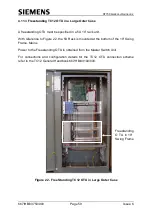
4.11.2 Free Standing TC12 OTU in Small Outer Case
The freestanding OTU must be specified in
a 5U 11” rack unit.
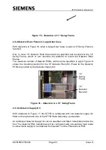
With reference to Figure 21, the 5U Rack is mounted at the bottom of an 1
1” Swing
Frame.
Mains Power to the Freestanding OTU is obtained from the Master Switch Unit.
For full connections and configuration details for the Tele 12 OTU connection
scheme refer to the Tele 12 General Handbook 667/HB/43100/000.

