


ST750
G
ENERAL
H
ANDBOOK
667/HB/33750/000
Page 71
Issue 6
the large controller cabinet base and 2.0 Litres for the small controller cabinet base
this will give an adequate and even cover.
This will act as a preventative barrier against the ingress of moisture and
animal/insect infestation.
A concrete fillet around the outside of the stool may be completed before or after the
epoxy sealing to suit site conditions.
Refer to Figure 24 and Figure 25 for general method of in-fill, kiln dried sand,
sealing and concrete fillet.
Warning!
Should the controller cabinet base/stool NOT be in-filled with kiln
dried sand and sealed with an approved epoxy resin the
controller electronics/electrical circuits may be damaged.
5.11 CABLE ROUTING & TERMINATION
The following guidelines apply when the ST750 Rack Assembly is installed in the
ST750 Cabinet Assembly or any other controller cabinet.
All intersection cables and their wires must secured within the cabinet using ty-
wraps once terminated.
Note:
No wire runs or looms should be positioned directly above the ST750 Rack
Assembly, as this would prevent its removal for maintenance or replacement. In the
back of the metal frame across the top of the ST750 Rack Assembly, securing holes
are provided to secure the detector wire looms. These holes ensure that there is
sufficient room to allow the removal of the ST750 Rack Assembly.
Wiring runs should be made neatly and routed to allow enough spare cables for
possible changes/additions at a later date.
Spare cores are to be bundled and routed to a convenient position clear of mains.
The ends are to be insulated to make the loom secured. Spare cores of ELV cables
are to be loomed separately from the cores of LV cables.
If cable idents are required then these are fitted to cores before termination.
Signal and Detector terminations to the ST750 Rack Assembly
should be as per
the Works Specification, leaving sufficient spare wire to enable joints to be remade
when necessary. The ‘Pair’ cable used for connection from the loops should be
terminated using the appropriate kit.
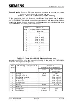
OMU must monitor the Controller Lamp Supply
at the screw terminal on SK2 Pin
6.