


ST750
G
ENERAL
H
ANDBOOK
667/HB/33750/000
Page 83
Issue 6
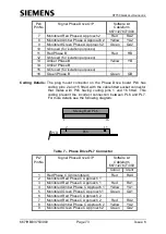
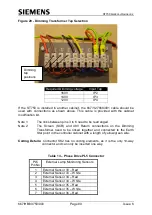
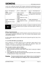
Also, the connectors PL2, PL3, PL6 and PL7 require a small-ended
(2.5mm) screwdriver. Use a Phoenix Screwdriver Part Number SZS
0.4 x 2,5 or equivalent (see note at the top of each table).
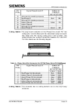
When installing in any other cabinet, a Softwire kit is required. Wire the loose wire
ends of the Softwire kit cableform to the terminal blocks in the cabinet, using the
relevant signals as defined by the works specification and shown in the tables that
follow:
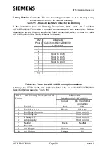
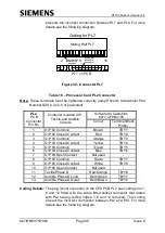
Table 14
– Processor Card PL3 Connector
Note:
These terminals must be tightened correctly, using Phoenix Screwdriver Part
Number SZS 0.4 x 2,5 or equivalent.
PL3
PCB
Connector
Pin No
Controller Isolated O/P,
Tactile and Audible
Circuits
Softwire Kit Cableform
667/1/27863/100
Colour
Terminal Block
Pin No
1
O/P 88 Common
Brown
TBX1
2
O/P 88 Closed Contact
Red
TBX2
3
O/P 89 Common
Orange
TBX3
4
O/P 89 Closed Contact
Yellow
TBX4
5
O/P 90 Common
Green
TBX5
6
O/P 90 Closed Contact
Blue
TBX6
7
O/P 90 Open Contact
Not used
-
8
O/P 91 Common
Slate
TBX7
9
O/P 91 Closed Contact
White
TBX8
10
O/P 91 Open Contact
Not used
-
11
Tactile Phase B
Red/Orange
TBX10
12
Audible Phase B Loud
Red/Green
TBX11
13
Audible Phase B Quiet
Red/Brown
TBX12
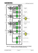
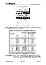
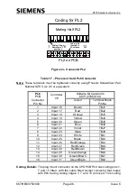
Coding Details:
The plug mount connector on the CPU PCB PL3 has coding pins 2,
8 and 13 fitted, with the cable fitted socket connector that mates with
PL3 having coding ridges 2, 8 and 13 removed. This coding prevent
the incorrect connection between PL3 and PL2. For more details
see the following diagram: