


ST750
G
ENERAL
H
ANDBOOK
667/HB/33750/000
Page 111
Issue 6
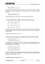
Dim L/Supply=160V
•
Checks all of the triacs in turn by applying a very short pulse to each
phase’s colour:
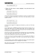
A/Red:Extra Sigs On
R-000000001
A-000000001
G-000000001
A fault will be logged if extra signals are detected as on when one particular aspect
is pulsed. This would normally imply a short-circuit in the street cabling or a open
neutral connection.
No Voltages On...
R-000000000
A-00000000A
G-000000000
A fault will also be logged if no voltages were detected, e.g. when one of the fuses
has blown.
In the example above, 0000000A represents phases B and D (see Figure 41), so
Amber (from RAG down the left-hand side) shows that the pedestrian Wait
indicators have no voltages present. Check the fuses F6 and F8 and the 48V output
from the dimming transformer for example.
If the link on the CPU Card selects the 'fail to flashing' option, the controller flashes
the red and amber phase mimic LEDs on the CPU card (section 4.3) for five
seconds before displaying the multicoloured scrolling pattern.
At the end of the test, the self-test switches off the lamp supply and displays a
multicoloured scrolling pattern on the LEDs to show that all the tests have passed
successfully.
It also illuminates a series of LEDs to identify which cards on the extended system
bus have been detected. A full list is displayed on the handset.
After a few seconds, self-test will repeat the second part of the self-test allowing the
controller to be soak tested.