


ST750
G
ENERAL
H
ANDBOOK
667/HB/33750/000
Page 88
Issue 6
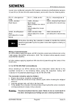
5.13.1 CPU PCB Switch and Link Setup
See the following pages for switch and link settings.
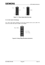
Figure 35
– CPU PCB
FUSE
FUSE
BATTERY
D
IL
S
w
D
IL
S
w
D
IL
S
w
D
IL
S
w
Modem
Port
PL12
Phase
Control
Bus
PL4
Manual Panel
Connector PL1
Controller
O/P 88 to 91
Controller O/P
92 to 95
Controller
I/P 0 to 15
Controller
I/P 16 to 31
Detector
Supply
Extended
System
Bus
PL11
S1
S3
S2
S4
PP
SE
WD
EPLD
Phase Bus
Processor &
Firmware
Main
Processor
Firmware
1st
2nd
Main
Processor
Phase
LED
Displays
A
B
C
D
E
F
Status
LED
Displays
LK1
Switches and Link
Setting Positions
RS232
Handset
Port
SK1
PL2
PL3
PL6
PL8
PL7