ST750
G
ENERAL
H
ANDBOOK
667/HB/33750/000
Page 38
Issue 6
This is often required, for example, when the pedestrian controller is close to an
intersection where it is beneficial to keep the pedestrian controller at vehicle green
during certain stages of the intersection controller to help the traffic entering and/or
leaving the nearby intersection.
Cableless Link
– Using the controller’s Master Time Clock and CLF facilities, the
controller can be given one or more ‘windows’ during the CLF cycle when it is
allowed to service the pedestrian demands. For the rest of cycle, the vehicle phase
remains at green.
UTC
– The ‘PV’ control bit from the instation holds the vehicle phase at green.
When the ‘PV’ bit is de-activated for a short period, the controller will service any
pending demand for the pedestrian phase.
Local Link
– The ‘PV1’ input from an adjacent controller holds the vehicle phase at
green. When the ‘PV1’ bit is de-activated for a short period, the controller will
service any pending demand for the pedestrian phase.
3.3 PEDESTRIAN DEMAND CONTROL
3.3.1 Introduction
In addition to pedestrian push buttons, the controller can be configured with ‘cycle
detectors’ and ‘kerbside detectors’. The controller firmware treats ‘cycle detectors’
and ‘push-button inputs’ the same and both should be configured to demand the
phase in the usual way.
‘Kerbside detectors’ allow the controller to cancel the demand (and switch off the
wait / demand indicator) if the pedestrian crosses before the pedestrian phase gains
right of way..
A push button input can be associated with a specific kerbside input in order to
determine the type of pedestrian demand inserted. A kerbside input can be
associated with one or more push button inputs, or it can be associated with none in
which case it is only used to hold and cancel the demand.
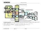
Figure 2
– Ped Demand Processing” overleaf shows the pedestrian demand
processing performed by the firmware described in the rest of this section.


