ST750
G
ENERAL
H
ANDBOOK
667/HB/33750/000
Page 46
Issue 6
4.2 The ST750 Rack Assembly
Figure 6
– ST750 Rack Assembly
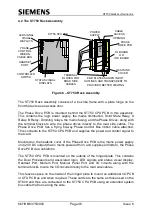
The ST750 Rack Assembly consists of a box like frame with a plate hinge on the
front that acts as an access door.
The Phase Drive PCB is mounted behind the ST750 CPU PCB in this assembly.
This contains the logic power supply, the mains distribution, Solid State Relay, A
Relay, B Relay, Dimming relays, the mains fusing, and the Phase Drives, along with
the terminal blocks to wire the phase drives directly to the road side cables. The
Phase Drive PCB has a flying 64-way Phase Control Bus ribbon cable attached.
This connects to the ST750 CPU PCB and supplies the power and control signal to
that card.
Mounted on the heatsink cover of the Phase Drive PCB is the mains power supply
unit (24V DC output) that is mains powered from, and supplies 24Volts to, the Phase
Drive PCB via a cableform.
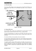
The ST750 CPU PCB is mounted on the outside of the hinged plate. This contains
the Dual Processors and associated logic, LED signals and status visual display,
Handset Port, Modem Port, Manual Panel Port and I/O circuits along with the
terminal blocks to wire the I/O circuits directly to the road side cables.
This leaves space on the inside of the hinged plate to mount an additional I/O PCB
or OTU PCB as and when required. These cards are the same as those used on the
ST800 and thus are connected to the ST750 CPU PCB using an extended system
bus cable that runs along the side.
P
S
U
END PLATES SHOWN IN DOT
OUTLINES AND TRANSPARENT TO
PROVIDED BETTER VIEWING
S
IE
M
E
N
S
S
T
7
5
0
ON
ST750 CPU PCB
PHASE
DRIVE PCB
HEATSINK
COVER
POWER
SUPPLY
I/O BOARD
OR
OTU BOARD
CONTROLLER
SWITCH
LED SIGNAL
VISUAL
DISPLAYS
HANDSET
PORT
CABLE
ACCESS
OPENING
TERMINAL
BLOCKS FOR
ROAD SIDE
CABLES
PHASE
CONTROL
RIBBON
CABLE BUS
STATUS VISUAL
DISPLAYS

